Steel ball flow polishing machine

A polishing machine and steel ball technology, applied in the field of mechanical processing, can solve problems such as unsatisfactory equipment, and achieve the effects of improving surface finish, low energy consumption, and optimizing production lines

Pending Publication Date: 2017-11-17
苏州斯曼克磨粒流设备有限公司
View PDF8 Cites 1 Cited by
  • Summary
  • Abstract
  • Description
  • Claims
  • Application Information

AI Technical Summary

Problems solved by technology

With the high requirements for product quality and process reliability, existing equipment can no longer meet

Method used


Image

  • Steel ball flow polishing machine
  • Steel ball flow polishing machine

Examples


Embodiment Construction

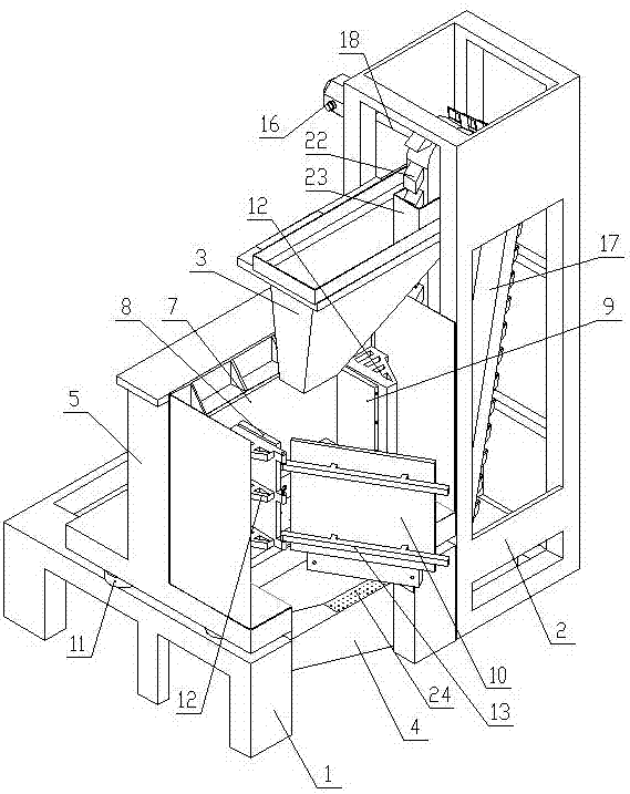
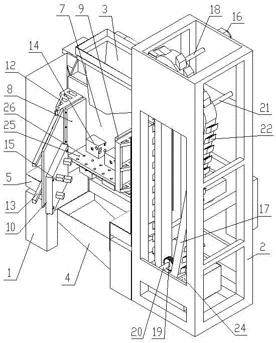
[0023] Such as figure 1 and figure 2 As shown, the steel ball flow polishing machine of the present invention includes a frame 1, which is provided with a workpiece mounting vibration container assembly, and the top and bottom of the workpiece mounting vibration container assembly are respectively provided with a steel ball inlet and a steel ball outlet, and the right side of the frame 1 The frame 2 in the shape of a cuboid is fixedly installed, and the upper left side of the upper part of the frame 2 is fixedly installed with an upper funnel 3 located above the steel ball inlet. , the frame 1 is provided with a lower funnel 4 located below the outlet of the steel balls, the lower funnel 4 is arranged with a high left and a right low slope, the lowest point inside the lower funnel 4 is located at the lower part of the frame 2, and a steel ball hanging and lifting mechanism is arranged in the frame 2 The left side of the upper part of the steel ball hanging and lifting mechan...


PUM


Abstract

Provided is a steel ball flow polishing machine. The machine comprises a rack, a workpiece mounting vibration container component is arranged on the rack, a steel ball inlet and a steel ball outlet are formed in the top and the bottom of the workpiece mounting vibration container component respectively, and a cuboid-shaped frame is fixedly arranged on the right side of the rack; an upper hopper located above the steel ball inlet is fixedly arranged on the left side of the upper portion of the frame, the bottom of the upper hopper is slantly arranged with the left lower than the right, and the right side of the top of the upper hopper is located on the upper portion in the frame; a lower hopper located below the steel ball outlet is arranged on the rack, the lower hopper is slantly arranged with the left higher than the right, the lowest portion in the lower hopper is located on the lower portion in the frame, and a steel ball hanging and lifting mechanism is arranged in the frame. The steel ball flow polishing machine can be used for removing chips of the workpiece of a complicated structure, can conduct chip removing, cleaning and rust removal at the same time and can improve the surface finish degree of the shiny side of the workpiece; no workpiece deforms after being machined, and second cleaning is not needed; multiple products can be machined at the same time, and the steel ball flow polishing machine can be matched with mechanical arms to achieve production line optimization, and is low in energy consumption, environmentally friendly and pollution free.

Description

technical field [0001] The invention belongs to the field of mechanical processing, in particular to a steel ball flow polishing machine. Background technique [0002] In recent years, with the upgrading of mechanical equipment in the field of mechanical processing, the performance of cutting processing has been greatly improved, but for the deburring of inner holes, special-shaped holes, cross holes, etc. It still stays in abrasive flow polishing, chemical polishing, thermal energy polishing, high-speed flow polishing and other processes, which have problems such as easy residue, non-environmental protection, and variability. With the high demands on product quality and process reliability, existing equipment could no longer meet them. Contents of the invention [0003] In order to solve the deficiencies in the prior art, the present invention provides a steel ball flow polishing machine with low cost, no pollution, no residue, and can improve the roughness of the surfac...

Claims


Application Information

Patent Timeline
Patent Type & Authority Applications(China)
IPC IPC(8): B24B31/06B24B31/00B24B31/12B24B31/14B24B55/03B24B55/00B24B41/02
CPCB24B31/003B24B31/006B24B31/06B24B31/12B24B31/14B24B41/02B24B55/00B24B55/03
Inventor 刘绍敏解高超白冠军
Owner 苏州斯曼克磨粒流设备有限公司
Why Eureka
Try Eureka