Non-contact zero-leakage sealing ring and sealing device thereof

A sealing device and sealing ring technology, applied in the direction of engine sealing, transmission parts, engine components, etc., can solve the problems such as the average service life of the seal is less than 6 months, the leakage of lubricating oil is increased, and it is difficult to meet the use requirements.

Pending Publication Date: 2017-11-17
SICHUAN SUNNY SEAL
View PDF10 Cites 1 Cited by
  • Summary
  • Abstract
  • Description
  • Claims
  • Application Information

AI Technical Summary

Problems solved by technology

Traditionally, single-end contact mechanical seals are used, but since the sealing speed can reach more than 20,000rpm, a large amount of frictional heat will be generated on the sealing end face during operation. Under the condition of no external flushing, the generated heat will accumulate on the sealing end area It is not easy to take away, and it is easy to cause blisters on the sealing graphite ring, resulting in increased leakage of lubricating oil
Although the mechanical seal design has been continuously optimized, the average service life of the seal is generally less than 6 months and unstable, which is difficult to meet the use requirements

Method used


Image

  • Non-contact zero-leakage sealing ring and sealing device thereof
  • Non-contact zero-leakage sealing ring and sealing device thereof
  • Non-contact zero-leakage sealing ring and sealing device thereof

Examples


Embodiment Construction

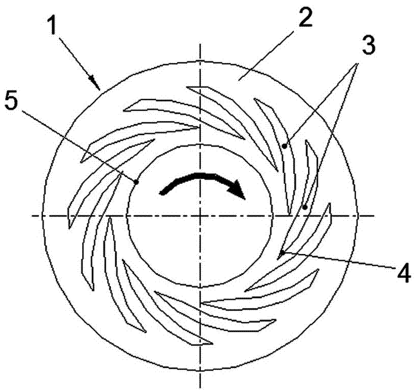
[0012] figure 1 Shown is the basic structure of a non-contact and zero-leakage single-rotation sealing ring of the present invention. A fluid dynamic pressure groove 3 lower than the end plane is arranged on the sealing end surface 2 of the sealing ring 1 . The fluid dynamic pressure groove 3 is arranged in the radially inner part of the sealing end surface that can communicate with the atmosphere, and the direction from the radially inner side to the radially outer side on the sealing end surface is a single-rotation direction opposite to the rotation direction of the sealing ring. groove. The specific form of the single-rotation groove can be designed according to the current conventional method according to the actual use needs. Wherein, the two ends of its hydrodynamic pressure tank 3 are divided as figure 1 In addition to the non-penetrating form that is respectively located within the inner and outer peripheral edges of the sealing end face as shown, a form in which t...


PUM


Abstract

The invention provides a non-contact zero-leakage sealing ring and a sealing device thereof. Each sealing end face of the sealing ring is provided with fluid dynamic pressure slots lower than the end plane. The fluid dynamic pressure slots are formed in the positions, on the radial inner side communicating with the atmosphere, in the sealing end face, and the trends, from the radial inner side to the radial outer side, of the fluid dynamic pressure slots in the sealing end face are opposite to the rotation direction of the sealing ring. According to the sealing ring, the theories of a traditional mechanical sealing ring and a dry gas sealing ring are combined, dynamic balance between the leakage pressure of the liquid medium side between the sealing end faces and the pressure of atmosphere entering reversely on the other side is achieved in a middle area of the sealing end faces, thus, continuous leakage of a liquid medium and continuous entering of the atmosphere are prevented, and the using requirements for extremely-low leakage amount and long service life are met.

Description

technical field [0001] The invention relates to a non-contact zero-leakage sealing ring and a sealing device thereof which are particularly applicable to, but not limited to, a high-speed pump speed-increasing gearbox. Background technique [0002] The end face mechanical seal is a type of dynamic sealing structure / device that has been widely used at present. Taking the high-speed pump speed-up gearbox as an example, the high-speed pump is driven by "motor + speed-up gearbox", and its layout has two types: horizontal and vertical. The shaft end of the high-speed output shaft of the speed-increasing gearbox needs to be equipped with a set of sealing devices to prevent the gearbox lubricating oil from leaking to the atmosphere. The working pressure of the sealing device is generally less than 0.2MPa, but the speed can be as high as 10,000 revolutions per minute, and the space of the sealing chamber is very compact. Traditionally, single-end contact mechanical seals are used,...

Claims


Application Information

Patent Timeline
Patent Type & Authority Applications(China)
IPC IPC(8): F16H57/029F16J15/38F16J15/40
CPCF16H57/029F16J15/38F16J15/40
Inventor 王泽平刘婷唐正明向前孙登波段剑锐
Owner SICHUAN SUNNY SEAL
Why Eureka
Try Eureka