Ink scraper grinding machine and using method thereof

A scraper and ink technology, which is applied in the directions of grinding machine parts, grinding machines, and grinding feed movements, can solve the problem of difficulty in completing scraper grinding, and achieves improved grinding quality, improved grinding accuracy, and reduced The effect of the support area

Active Publication Date: 2017-11-24
马鞍山俊强精密机械设备有限公司
View PDF5 Cites 4 Cited by
  • Summary
  • Abstract
  • Description
  • Claims
  • Application Information

AI Technical Summary

Problems solved by technology

[0007] Aiming at the problem that the existing ink scraper grinding device is difficult to complete the grinding p

Method used


Image

  • Ink scraper grinding machine and using method thereof
  • Ink scraper grinding machine and using method thereof
  • Ink scraper grinding machine and using method thereof

Examples


Embodiment 1

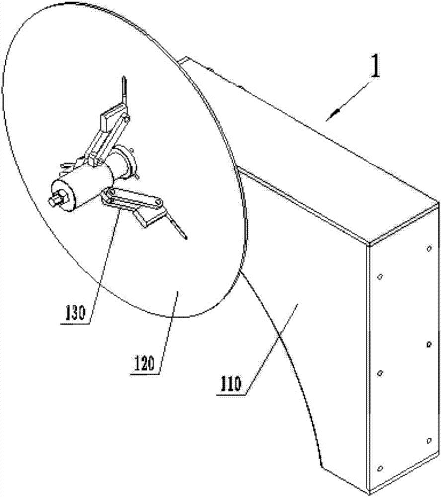
[0058] Such as image 3 , Figure 4 , Figure 5 As shown, a steel strip unwinding device in this embodiment is used for clamping ink scrapers or other soft steel strip coils for grinding with a grinder, which mainly includes a base 110, a rotating shaft 140, and a turntable 120 and clamping mechanism 130.

[0059] Wherein, the base 110 is an L-shaped box structure welded by plates, and the rotating shaft 140 is mainly composed of three sections, which are respectively a supporting section 141 , a limiting section 142 and a guide adjusting section 143 from one end to the other end. Two coaxial belt seat bearings 150 are installed on the front and back sides of the L-shaped box left end, and the support section 141 of the rotating shaft 140 is supported and installed in the two belt seat bearings 150, thereby the rotating shaft 140 rotating shaft can be supported to rotate. The limit section 142 is located in the middle of the rotating shaft 140, and its diameter is larger th...

Embodiment 2

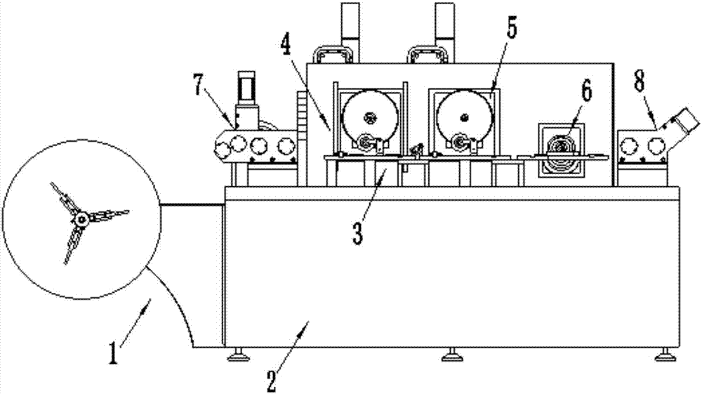
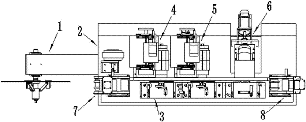
[0067] Such as figure 1 and figure 2 As shown, an ink scraper grinding machine tool in this embodiment mainly includes a frame 2, a workbench assembly 3, a steel strip unwinding device 1, a brake assembly 7, a surface grinding assembly, an edge grinding assembly 6 and a drive assembly 8 ; Wherein, the steel strip unwinding device 1 adopts the steel strip unwinding device in Embodiment 1, which is installed on the left side of the frame 2 by the base 110, the brake assembly 7, the plane grinding assembly, the edge grinding Components 6 and drive components 8 are arranged sequentially on the machine frame 2 along the processing direction, that is, arranged from left to right, and the workbench component 3 is installed on the frame 2 corresponding to the plane grinding component and the edge grinding component 6 s position. Specifically in this machine tool, the functions of each part are: the workbench assembly 3 is used to support the steel belt of the ink scraper, the surfa...


PUM


Abstract

The invention discloses an ink scraper grinding machine and a using method thereof and belongs to the field of grinding machines. A workbench assembly of the grinding machine is arranged on a machine frame and used for supporting an ink scraper. A plane grinding assembly is used for grinding the surface of the ink scraper. A cutting edge grinding assembly is used for grinding a cutting edge of the ink scraper. A steel strip coiling device is used for clamping a to-be-machined steel coil. A brake assembly is used for controlling the ink scraper for braking and correcting the smoothness of the ink scraper while the ink scraper is delivered. A drive assembly is used for driving the ink scraper to be fed. The brake assembly, the plane grinding assembly, the cutting edge grinding assembly and the drive assembly are sequentially arranged on the machine frame in the machining direction. The ink scraper grinding machine can complete grinding of the surface and the cutting edge of a flexible steel strip, and straighten the steel strip before grinding of the steel strip so as to ensure the surface smoothness. By means of the method, the surface and the cutting edge of the steel coil of the oil scraper can be ground quickly and efficiently.

Description

technical field [0001] The invention belongs to the field of grinding machines, and designs a grinding machine for processing ink scrapers, more specifically, relates to an ink scraper grinding machine and a method for using the same. Background technique [0002] Ink scraper is a long thin blade widely used in papermaking, printing, packaging and other fields. It is often made of alloy tool steel with good strength and hardness. For ink scrapers, the general edge accuracy requires good straightness, uniform thickness, and a mirror effect on the surface, so a grinding process must be used. For example, it is used on printing presses to scrape off excess ink on the surface of the printing cylinder. A good fit between them can ensure the high quality of printing. High-quality ink scrapers are usually made of carbon steel or stainless steel, and their thickness is usually 0.15 to 0.6mm. The length varies according to the length of different printing press cylinders. The blade...

Claims


Application Information

Patent Timeline
IPC IPC(8): B24B27/00B24B3/00B24B41/00B24B41/06
CPCB24B3/00B24B27/0076B24B41/00B24B41/005B24B41/06Y02P70/10
Inventor 邓兵张祥想
Owner 马鞍山俊强精密机械设备有限公司
Why Eureka
Try Eureka