Ultra wideband differential antenna with reconfigurable trapped wave
An ultra-wideband and antenna technology, applied in the field of ultra-wideband differential antennas, can solve the problems of increased communication system cost, low antenna gain, large antenna size, etc., and achieve the effect of compact structure, small size, and easy control
- Summary
- Abstract
- Description
- Claims
- Application Information
AI Technical Summary
Problems solved by technology
Method used
Image
Examples
Embodiment 1
[0023] Embodiment 1: An ultra-wideband differential antenna with a notch center operating frequency of 5.5 GHz.
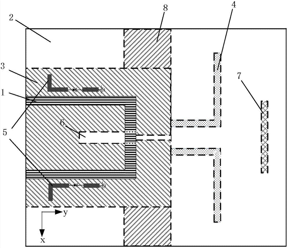
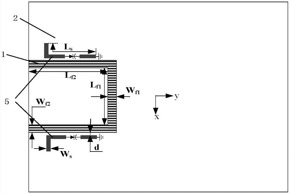
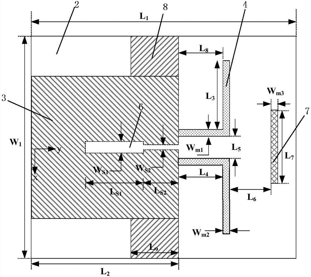
[0024] refer to figure 1 , figure 2 with image 3 , the notched reconfigurable UWB differential antenna in this example includes a microstrip feeder 1, a microstrip dielectric substrate 2, a metal ground plate 3, a radiation element 4, two microstrip short-circuit stubs 5, and a slot line Structure 6, one director 7 and two reflectors 8.
[0025] The microstrip feeder 1 is a U-shaped differential input port. The U-shaped differential input port is composed of two 50-ohm microstrip vertical lines connected to a microstrip horizontal line. The two 50-ohm microstrip vertical lines are used for The differential signal is transmitted, and a microstrip horizontal line in the middle is used as the bottom edge of the U shape, which is used to feed the slot line structure 6 at the bottom, so as to realize the transmission of the differential mode signal and the suppress...
Embodiment 2
[0032] Embodiment 2: An ultra-wideband differential antenna with a notch center operating frequency of 6.2 GHz.
[0033] The structure of this example is the same as that of Example 1, including a microstrip feeder 1, a microstrip dielectric substrate 2, a metal ground plate 3, a radiation unit 4, two microstrip short-circuit stubs 5, and a slot line structure 6 , a director 7 and two reflectors 8, the difference lies in that the structural parameters change. in:
[0034] The length L of the uniform impedance resonator s Taking the center frequency of the notch in this example as a quarter wavelength of 6.2GHz, it is approximately 8.04mm, so the control voltage at both ends of the varactor diode is 10V.
[0035] The length L of the microstrip horizontal line of the U-shaped differential input port f1 14.6mm, line width W f1 1.9mm;
[0036] The length L of two 50-ohm microstrip vertical lines of the U-shaped differential input port f2 15.8mm, line width W f2 1.8mm;
[0...
Embodiment 3
[0044] Embodiment 3: An ultra-wideband differential antenna with a notch center operating frequency of 6.6 GHz.
[0045] The structure of this example is the same as that of Example 1, including a microstrip feeder 1, a microstrip dielectric substrate 2, a metal ground plate 3, a radiation unit 4, two microstrip short-circuit stubs 5, and a slot line structure 6 , a director 7 and two reflectors 8, the difference lies in that the structural parameters change. in:
[0046] The length L of the uniform impedance resonator s Taking the center frequency of the notch wave in this example as a quarter wavelength of 6.6GHz, it is approximately 7.6mm, so the control voltage at both ends of the varactor diode is 30V.
[0047] The length L of the microstrip horizontal line of the U-shaped differential input port f1 14.0mm, line width W f1 2.1mm;
[0048] The length L of two parallel 50 ohm microstrip vertical lines of the U-shaped differential input port f2 16mm, line width W f2 1...
PUM
 Abstract
Description
Claims
Application Information
 - R&D
- Intellectual Property
- Life Sciences
- Materials
- Tech Scout
- Unparalleled Data Quality
- Higher Quality Content
- 60% Fewer Hallucinations
Browse by: Latest US Patents, China's latest patents, Technical Efficacy Thesaurus, Application Domain, Technology Topic, Popular Technical Reports.
© 2025 PatSnap. All rights reserved.Legal|Privacy policy|Modern Slavery Act Transparency Statement|Sitemap|About US| Contact US: help@patsnap.com


