Anti-fogging and Anti-fouling laminate and method for producing same, article and method for producing same, and Anti-fouling method

A manufacturing method and anti-fouling layer technology, applied in lamination, layered products, lamination devices, etc., can solve problems such as low manufacturing efficiency

Inactive Publication Date: 2017-11-28
DEXERIALS CORP
View PDF5 Cites 5 Cited by
  • Summary
  • Abstract
  • Description
  • Claims
  • Application Information

AI Technical Summary

Problems solved by technology

[0006] However, in the proposed technique, since a microprotrusion structure is to be fabricated and a compound containing one or more atoms selected from fluorine atoms and silicon atoms is deposited thereon by chemical vapor treatment, there is a problem. The problem of low manufacturing efficiency

Method used


Image

  • Anti-fogging and Anti-fouling laminate and method for producing same, article and method for producing same, and Anti-fouling method
  • Anti-fogging and Anti-fouling laminate and method for producing same, article and method for producing same, and Anti-fouling method
  • Anti-fogging and Anti-fouling laminate and method for producing same, article and method for producing same, and Anti-fouling method

Examples


no. 1 Embodiment approach

[0241] The first embodiment is an example of the above-mentioned anti-fogging and anti-fouling layer forming process using a transfer original disk by using a photoresist having a predetermined pattern shape as a protective film on the transfer original disk. The surface is etched to form any of fine protrusions and recesses.

[0242] First, the transfer master and its manufacturing method will be described.

[0243] 〔Composition of the transfer master disk〕

[0244] Figure 3A It is a perspective view showing an example of the configuration of a roll master as a transfer master. Figure 3B will be Figure 3A An enlarged view of a portion of the roll master shown. Figure 3C Yes Figure 3B Profile plot in trajectory T. The roll master 231 is a transfer master for making the anti-fog and antifouling laminate with the above-mentioned structure, more specifically, the roll master 231 is used to form a plurality of Raw discs with convex or concave parts. The roll master 23...

no. 2 Embodiment approach

[0270] The second embodiment is an example of the above-mentioned anti-fogging and anti-fouling layer forming process using a transfer original disk formed by laser processing of the transfer original disk by irradiating a laser beam on the surface of the transfer original disk. Any of the fine protrusions and recesses is formed.

[0271] First, the transfer master and its manufacturing method will be described.

[0272] 〔Composition of the transfer master disk〕

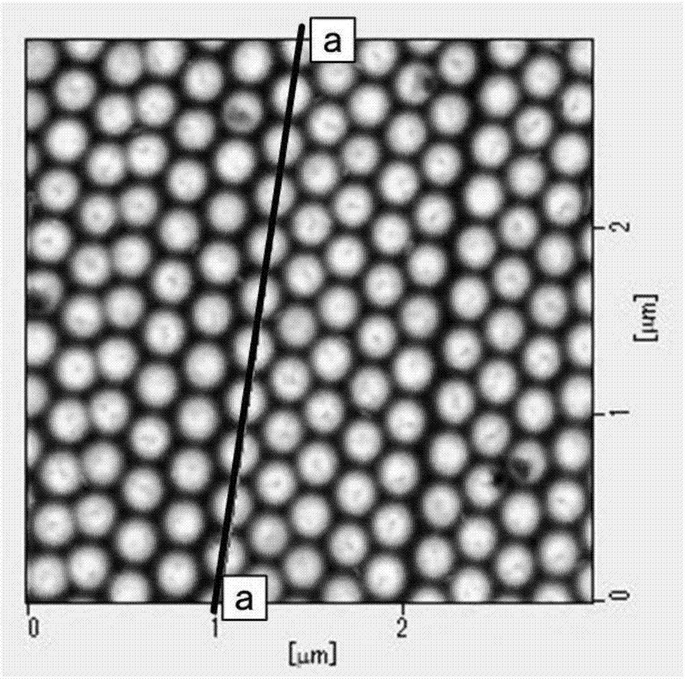
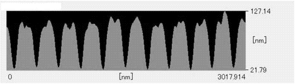
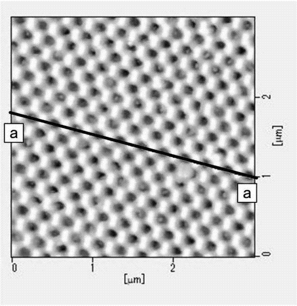
[0273] Figure 7A It is a plan view showing an example of the configuration of a plate-shaped original disk. Figure 7B is along Figure 7A The section view of line a-a is shown. Figure 7C will be Figure 7B Sectional view showing enlarged part of . The plate-shaped master 331 is a master for producing the anti-fog and anti-fouling laminated body having the above-mentioned structure. Or the original disk of the concave part. The plate-shaped master 331 has, for example, a surface provided with a fine concave-c...

Embodiment 1

[0423]

[0424] First, a glass roll master with an outer diameter of 126 mm was prepared, and a resist layer was formed on the surface of the glass roll master as follows. That is, the photoresist is diluted with a diluent at a mass ratio of 1 / 10, and the diluted resist is coated on the cylindrical surface of the glass roll master by a dipping method so that the average thickness becomes about 70 nm, thereby forming a resist Floor. Next, transport the glass roll master to the Figure 4 In the roll master exposure device shown in the figure, the resist layer is exposed to form a helical shape, and at the same time, a latent image of a hexagonal pattern is formed between three adjacent lines of tracks and is patterned on the resist layer. . Specifically, a laser beam of 0.50 mW / m was irradiated to a region where a hexagonal grid exposure pattern should be formed to form a hexagonal grid exposure pattern.

[0425]Next, developing treatment is performed on the resist layer on...


PUM

PropertyMeasurementUnit
contact angleaaaaaaaaaa
hardnessaaaaaaaaaa
hardnessaaaaaaaaaa

Abstract

An anti-fogging and anti-fouling laminate comprising a resin-made base material and an anti-fogging and anti-fouling layer formed on the resin-made base material, wherein the anti-fogging and anti-fouling layer has fine protrusions or depressions on the surface thereof, the anti-fogging and anti-fouling layer contains a hydrophilic molecular structure, and the pure water contact angle on the surface of the anti-fogging and anti-fouling layer is 90o or more.

Description

technical field [0001] The present invention relates to an anti-fog and anti-fouling laminated body and a manufacturing method thereof. It is used in a wide range of battery panels and the like, and is easy to be molded; an article using the above-mentioned anti-fog and anti-fouling laminate and its manufacturing method; and an anti-fouling method using the above-mentioned anti-fog and anti-fouling laminate. Background technique [0002] Among various articles, resin film, glass, etc. are attached to the surface in order to decorate and protect the surface. [0003] However, sometimes the visibility and aesthetics of the item may be reduced due to blurring and dirt of the resin film, glass, etc. that decorate and protect the surface of the item. [0004] Therefore, in order to prevent the deterioration of the visibility and appearance of such articles, the above-mentioned resin film and glass are subjected to hydrophobization treatment. [0005] As a hydrophobization treat...

Claims


Application Information

Patent Timeline
Patent Type & Authority Applications(China)
IPC IPC(8): B32B3/30B29C45/16B32B27/00B32B37/15
CPCB32B27/00B32B37/15B29K2995/0093B29C37/0032B29C59/046B29C2035/0822B29C2035/0827B29C2037/0042B29C2059/023B32B33/00B32B2038/0076B32B2307/40B32B3/30B29K2669/00B29K2995/0092B29L2009/00B32B2307/728B32B7/12B32B27/08B32B23/08B32B2250/02B32B2250/24B32B23/20B32B27/36B32B27/281B32B27/34B32B27/32B32B27/308B32B27/285B32B27/288B32B27/304B32B27/365B32B27/38B32B27/42B32B27/40B32B27/302B32B27/325B32B2270/00B32B2307/7242B32B2307/412B32B2307/75B32B2307/584B32B2307/306B32B2307/73B32B2307/51B32B2307/536B32B2307/756B32B2419/00B32B2605/003B32B2551/08B32B2457/12B29C45/16B29C59/026
Inventor 水野幹久原忍坂本祥吾远藤亮介岩村贡
Owner DEXERIALS CORP
Why Eureka
Try Eureka