Server rack and server cooling device
A cooling device and server technology, applied in the rack/frame structure, cooling/ventilation/heating transformation, instruments, etc., to achieve efficient cooling, avoid stagnation, and avoid losses
- Summary
- Abstract
- Description
- Claims
- Application Information
AI Technical Summary
Problems solved by technology
Method used
Image
Examples
Embodiment 1
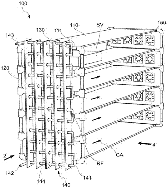
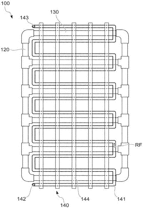
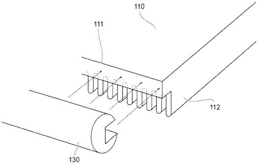
[0076] The following will be used as the server rack 100 and the server cooling device SC according to the first embodiment of the present invention. Figure 1~9 Be explained.
[0077] figure 1 It is a side view showing the outline of the server rack 100 as the first embodiment of the present invention.
[0078] figure 2 From figure 1 A front view showing the outline of the air cooler 140 of the server rack 100 viewed from reference numeral 2 .
[0079] image 3 is an exploded side view of the panel 110 and beam 130 .
[0080] Figure 4 From figure 1 A schematic side view of the server rack 100 viewed from reference numeral 4 .
[0081] Figure 5 is a side view showing the installation position of the side panel 160.
[0082] Figure 6 It is a conceptual diagram showing the overall appearance of the server cooling system SC.
[0083] Figure 7 is a phase diagram showing the RF temperature-pressure characteristics of carbon dioxide.
[0084] Figure 8 It is a ...
Embodiment 2
[0121] In the second embodiment 2 of the present invention, the server rack 200 consists of Figure 10 exhibit.
[0122] Figure 10 A front view of the server rack 200 showing the outline of the air cooler 240 is shown.
[0123] The server rack 200 changes the air cooler 140 of the server rack 100 in the first embodiment, the path of the refrigerant circuit 141 and the direction of the air cooling louvers 144, many elements are common to the server rack 100 of the first embodiment, Therefore, the common items are omitted, and the last two digits after the number 200 are the common symbols.
[0124] Figure 10 As shown, the refrigerant circuit 241 of the air cooler 240 of the server rack 200 is branched from the refrigerant inlet 242 to the outlet 243 and extends toward the pillar installation direction (upper direction) and merges.
[0125] The air cooling louvers 244 are arranged in the horizontal direction.
[0126] The air humidity in the server room is not high, and t...
Embodiment 3
[0128] In the third embodiment of the present invention, the overall SC of the server cooling device consists of Figure 11 exhibit.
[0129] Figure 11 It is an overall conceptual diagram of the server cooling system SC.
[0130] In the server cooling device SC of the third embodiment, the heat exchanger of the server cooling device SC in the first embodiment is changed, and many elements are in common with the first embodiment, so the description of the common items is omitted.
[0131] Figure 11 As shown, the server cooling device SC consists of cascade condenser CC, low-pressure liquid receiver LLR, compressor CP, evaporative condenser EC, high-pressure liquid receiver HLR, expansion valve EX, liquid pump PP1, liquid pump PP2, carbon dioxide Liquid reservoir GLR, evaporator EV composition.
[0132] The cascade condenser CC cools and liquefies the gas refrigerant.
[0133] The liquid pump PP1 transports the liquid refrigerant from the low-pressure liquid receiver LLR ...
PUM
 Abstract
Description
Claims
Application Information
 - R&D
- Intellectual Property
- Life Sciences
- Materials
- Tech Scout
- Unparalleled Data Quality
- Higher Quality Content
- 60% Fewer Hallucinations
Browse by: Latest US Patents, China's latest patents, Technical Efficacy Thesaurus, Application Domain, Technology Topic, Popular Technical Reports.
© 2025 PatSnap. All rights reserved.Legal|Privacy policy|Modern Slavery Act Transparency Statement|Sitemap|About US| Contact US: help@patsnap.com


