Clean and efficient gasifying device for coke Y-shape entrained-flow bed

A technology of gasification device and entrained flow bed, which is applied in the field of coal chemical industry, and can solve problems such as weak centrifugal force, high material requirements for pressure-bearing shells, and complex structures.

Inactive Publication Date: 2017-12-01
CHINA UNIV OF PETROLEUM (EAST CHINA)
View PDF8 Cites 0 Cited by
  • Summary
  • Abstract
  • Description
  • Claims
  • Application Information

AI Technical Summary

Problems solved by technology

In practical applications, the performance is far superior to other synthetic entrained-bed gasifiers, but there are still difficulties and uneven slag hanging on the water-cooled wall, and it is easy to produce large pieces of slag, and hot slag water seals still form a large amount of difficult-to-treat saline wastewater , affecting long-term safe operation, poor cooling effect of gas circulation, high energy consumption, large investment, weak centrifugal effect of swirling cooling gas to drive syngas to rotate, and large gas volume, resulting in a substantial increase in the load of waste heat boilers, and the structure of the cooling spiral tube is not good Major defects and deficiencies, such as favorable side nozzle arrangement, complex structure, and high material requirements for the pressure-bearing shell, have affected the popularization and application of entrained bed gasifiers for solid phase slag removal

Method used


Image

  • Clean and efficient gasifying device for coke Y-shape entrained-flow bed

Examples


Embodiment Construction

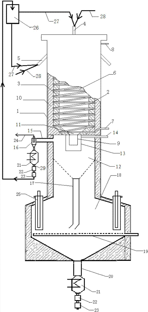
[0017] Below in conjunction with accompanying drawing, the present invention is described in detail: figure 1 As shown, the coal char Y-type entrained entrained gasification device of the present invention is composed of gasification furnace shell (1), cooling pipe (2), refractory material layer (3), top nozzle (4), side nozzle (5), reaction chamber (6), coolant inlet (7), coolant outlet (8), gasification product outlet (9), insulation material layer (10), segmented conical head (11), cooling Chamber (12), swirl cooling jacket (13), cold gas return port (14), gas outlet (15), solid slag discharge port (16), fluidized bed heat exchanger (18), moving bed heat exchanger (21), lock buckets (22, 23), raw material pulverized coal bins (26), etc.; cooling pipes (2) are installed around the inside of the gasifier shell (1), and the outside of the cooling pipes is an insulating material layer (10 ), the cooling pipe is fixed in the refractory material layer (3), and the reaction chamb...


PUM


Abstract

The invention provides a clean and efficient gasifying device for a coke Y-shape entrained-flow bed. The clean and efficient gasifying device mainly comprises a gasifying furnace, a gas-dust separator, a fluidized bed heat exchanger and movable bed heat exchangers, wherein the gasifying furnace is divided into a gasifying chamber and a chilling chamber, and the middle is separated through a subsection cone-shaped end socket; a shell of the gasifying chamber is sequentially provided with a thermal insulation material layer, a cooling jacket and a wear-resistant material layer from outside to inside; a cooling liquid inlet is formed in the bottom of the gasifying chamber, and a cooling liquid outlet is formed in the top of the gasifying chamber; a top nozzle is arranged in the center of the top of the gasifying chamber, and more than three side nozzles are uniformly arranged at the upper part of the gasifying chamber along the circumference; a gasifying product discharging hole is formed in the center of the subsection cone-shaped end socket and communicated into the chilling chamber; a chilling nozzle is arranged outside the gasifying product discharging hole, a solid slag discharging pipe is arranged in the center of the subsection cone-shaped end socket at the bottom of the chilling chamber and communicated into the fluidized bed heat exchanger, and rough synthesis gas outlet is formed in the upper part of the chilling chamber and is communicated into the gas-dust separator; and the movable bed heat exchangers and two-stage lock hopper dischargers are arranged at the outlets of the fluidized bed heat exchanger and the gas-dust separator. According to the efficient gasifying device, waste heat of gasifying products is adequately utilized, and the problems of black water and salt-containing wastewater are eliminated.

Description

1. Technical field [0001] The invention relates to the field of coal chemical industry, in particular, to gasification of gas flow bed. 2. Background technology [0002] Coal gasification is the leading and key technology for the clean and efficient utilization of coal. Entrained bed gasification is a new coal co-current gasification technology developed in recent decades. The gasification agent and coal powder or coal slurry enter the gasification chamber through the nozzle, and the pyrolysis, combustion and gasification reactions of coal proceed almost simultaneously. , The high temperature ensures the complete gasification of the coal, and the minerals in the coal become slag and leave the gasifier. Compared with the traditional gasification technology, the pressurized entrained entrained bed gasification temperature is higher, the processing capacity is larger, the gas active component is higher, and the gasification efficiency is higher, which is the development direct...

Claims


Application Information

Patent Timeline
IPC IPC(8): C10J3/48
CPCY02E20/18Y02P20/129C10J3/485C10J2200/152C10J2300/093C10J2300/0976
Inventor 田原宇乔英云
Owner CHINA UNIV OF PETROLEUM (EAST CHINA)
Why Eureka
Try Eureka