Lightweight design method for large-sized die-casting machine tail boards

A lightweight design, die-casting machine technology, applied in design optimization/simulation, calculation, multi-objective optimization, etc., can solve problems such as inability to effectively optimize design, complex force conditions, and difficult to obtain accurately. Process feasibility, effect of weight reduction, design and manufacturing cost reduction

Active Publication Date: 2017-12-01
INST OF INTELLIGENT MFG GUANGDONG ACAD OF SCI
View PDF7 Cites 9 Cited by
  • Summary
  • Abstract
  • Description
  • Claims
  • Application Information

AI Technical Summary

Problems solved by technology

The working process of the tail plate of the die-casting machine is subject to the joint action of the thrust of the machine hinge, the tension of the Gelin column, and the pressure of the oil cylinder. The force in the horizontal direction includes the force in the vertical direction. Since the influence of the deformation of the expansion mechanism cannot be considered, it is difficult to accurately obtain the magnitude of the load in each direction through theoretical calculation methods. The premise of light weight is to ensure the mechanical properties of the tail plate. There is no accurate If the load condition is used as the input condition, the optimal design cannot be effectively carried out
In addition, the material of the tail plate of a large die-casting machine is ductile iron. The overall structure is cast and produced in combination with subsequent mechanical processing. The lightweight process needs to consider the performance of the manufacturing process. For the tail plate structure that cannot be manufactured by the existing processing methods, even if it is re- Lightweight is pointless

Method used


Image

  • Lightweight design method for large-sized die-casting machine tail boards
  • Lightweight design method for large-sized die-casting machine tail boards
  • Lightweight design method for large-sized die-casting machine tail boards

Examples


Embodiment Construction

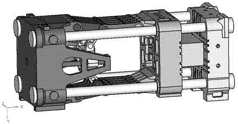
[0026] like figure 1 As shown, a lightweight design method for a tail plate of a large-scale die-casting machine in the present invention includes the following steps: S1: Establish a three-dimensional assembly model of the clamping mechanism of a large-scale die-casting machine through CAD software.

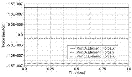
[0027] S2: Read in the 3D assembly model of the mold clamping mechanism through the multi-body dynamics simulation software, establish a virtual prototype of the mold clamping mechanism of the die-casting machine, perform kinematics simulation on the virtual prototype model, and draw the effect of the tail plate and the machine hinge The force curve and the force curve of the straight hinge and the movable mold seat plate.

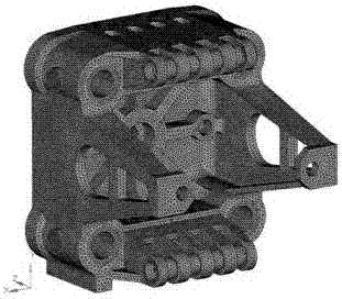
[0028] S3: Establish a discretized model of the tail plate of the die-casting machine through CAE software, take the force between the tail plate and the machine hinge as the input condition, conduct static stiffness analysis and modal analysis on the tail p...


PUM


Abstract

The invention discloses a lightweight design method for large-size die-casting machine tail boards. The lightweight design method includes building three-dimensional models through computer-aided cartography (CAC), building a virtual prototype (VPT) through multibody dynamic simulation software to perform simulation and to draw curves of acting force, subjecting existing tail boards, in reference types, of die clamping mechanisms to numerical simulation of static performance and dynamic performance through computer aided engineering (CAE), calculating to obtain the stress, the rigidity and the modal frequency threshold, defining the design space and the non-design space of the tail boards, searching the optimum load transmission path meeting requirements of critical threshold and large-sized tail board lightweight structure meeting requirements of processing technique, and finally building lightweight models by digitizing means, and performing analysis verification so as to realize the lightweight design on the large-sized die-casting machine tail boards. By comprehensive application of multiple digitizing design techniques and variable-density method based topological optimization design techniques, work efficiency of design staff can be improved, weight of the large-sized die-casting machine tail boards can be reduced, and processing feasibility is guaranteed.

Description

technical field [0001] The invention relates to the technical field of production design of a tail plate of a large die-casting machine, in particular to a lightweight design method for a tail plate of a large die-casting machine. Background technique [0002] Die-casting machine is the basic equipment of pressure casting. It is composed of mold clamping mechanism, injection mechanism and control system. National defense, rail transit and other industries. The mold clamping mechanism is composed of tail plate, machine hinge and movable mold seat plate. Its function not only provides thrust for the opening and closing of the mold, but also provides clamping force for the injection process. Each die casting production cycle is accompanied by the mold clamping mechanism. One opening and closing action, the mold clamping mechanism has a significant impact on the working efficiency, reliability and casting quality of the die casting machine. [0003] The traditional mold clampi...

Claims


Application Information

Patent Timeline
Patent Type & Authority Applications(China)
IPC IPC(8): G06F17/50
CPCG06F30/17G06F30/20G06F2111/04G06F2111/06
Inventor 张华伟陈启愉罗良传郭伟科陈敏
Owner INST OF INTELLIGENT MFG GUANGDONG ACAD OF SCI
Why Eureka
Try Eureka