Method and device for catalytic oxidation purification and energy utilization of low calorific value industrial tail gas

A technology for industrial tail gas and catalytic purification, which is applied in the fields of environmental protection and low-grade resource utilization, and can solve the problems of catalytic purification and energy utilization of low calorific value industrial tail gas, ineffective oxidation of combustible components, and wear-resistant granular catalysts. To achieve the effect of solving catalyst carbon deposition, improving environmental protection performance and energy recovery rate, and high safety and stability

Active Publication Date: 2020-04-21
YUNNAN PRECIOUS METALS LAB CO LTD
View PDF11 Cites 0 Cited by
  • Summary
  • Abstract
  • Description
  • Claims
  • Application Information

AI Technical Summary

Problems solved by technology

As disclosed in CN102974216A "Carbon Catalytic Reduction Treatment Method for Nitrous Oxide in Industrial Tail Gas" and "A Continuous Dearsenic Carbonization Agent and Preparation Method for Industrial Tail Gas Purification" disclosed in CN104624223A, still fail to solve the problem of low calorific value, Catalytic Purification and Energy Utilization of Low Concentration Industrial Exhaust Gas
In addition, the catalytic purification method is used to treat low calorific value and low concentration industrial exhaust gas. The granular catalyst in the prior art is not resistant to wear, has a short life (only about 3 years), high resistance, and low space velocity (5000h -1 Within), the catalyst is under the condition of anoxic condition, and the carbon deposition problem shortens the life of the catalyst, and the catalyst regeneration process to deal with the carbon deposition problem complicates the catalytic combustion process, increases the investment, and the adaptability of the catalyst is relatively weak, and the tail gas The combustible components in it cannot be effectively oxidized

Method used


Image

  • Method and device for catalytic oxidation purification and energy utilization of low calorific value industrial tail gas

Examples


Embodiment 1

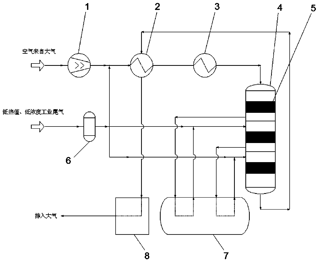
[0021] The flow rate is 500Nm 3 / h, the pressure is 41kpaG, the temperature is 35°C, the combustible component is 5% dust-free exhaust gas, and the 300Nm from the main pipe of the air compressor 3 / h, the pressure is 40 kPaG, after the air is fully mixed, it is heated to 350°C by starting the heater, and then sent to the catalytic reactor for complete catalytic oxidation and then heated to 489°C. The reactor inlet heater heats the inlet gas to 360°C, which itself is cooled and discharged to the atmosphere. The various components of the mixed gas leaving the catalytic reactor meet the national emission requirements. Due to the small gas volume and low pressure, there is no energy recovery value.

Embodiment 2

[0023] The flow rate is 24000Nm 3 / h, the pressure is 200kpaG, the temperature is 25°C, the total combustible components are 11% industrial tail gas, and the split flow is 8000Nm 3 / h and 15500Nm from the main pipe of the air compressor 3 / h, the pressure is 210kpaG, after the air is fully mixed, it is heated to 220°C by starting the heater, and sent to the first stage of the catalytic reactor for a complete catalytic oxidation reaction. While the mixed gas is purified, the reaction heat heats the mixed gas to 583°C , the high-temperature gas after the first-stage reaction passes through the waste heat boiler to recover heat and produce steam by-product, the temperature drops to 370°C, and then diverts the 8000Nm of the remaining tail gas 3 / h is fully mixed with the mixed gas after heat exchange at the outlet of the first stage, and sent to the second stage of the catalytic reactor for a complete catalytic oxidation reaction. While the mixed gas is purified, the reaction hea...

Embodiment 3

[0025] The flow rate is 40000Nm 3 / h, the pressure is 2000kpaG, the temperature is 23°C, the total combustible components are 15% industrial tail gas, and the split flow is 13000Nm 3 / h and 25500Nm from the main pipe of the air compressor 3 / h, the pressure is 2000kpaG, after the air is fully mixed, it is heated to 235°C by starting the heater, and then sent to the first stage of the catalytic reactor for a complete catalytic oxidation reaction. While the mixed gas is purified, the reaction heat heats the mixed gas to 590°C . After the first-stage reaction, the high-temperature gas passes through the waste heat boiler to recover the heat and produce steam by-product. The temperature drops to 310°C, and then the 13000Nm of the remaining tail gas is diverted. 3 / h is fully mixed with the mixed gas after heat exchange at the outlet of the first stage, and sent to the second stage of the catalytic reactor for complete catalytic oxidation reaction. While the mixed gas is purified,...


PUM


Abstract

The invention relates to a method for complete catalytic-oxidation purification and heat utilization of low-calorific-value industrial exhaust gas and a device. The device consists of an air compressor, a heat exchanger, a startup heater, a multistage-structure catalytic reactor, a catalyst, a dedusting purifier, an exhaust-heat boiler, heat utilization equipment, an assorted static mixer and detection and control components and parts. The low-calorific-value and low-concentration industrial exhaust gas is mixed with compressed air, then, the mixture enters the multistage-structure catalytic reactor, repeated catalytic-oxidation reactions are carried out through the catalytic action of the catalyst to purify the mixture, and heat and energy recovery is separately carried out according to differences of heat and exhaust gas pressures generated by the oxidation reactions. The low-calorific-value and low-concentration industrial exhaust gas is subjected to catalytic oxidation purification completely and then is exhausted into the atmosphere. According to the method and the device, the problems in the purification and heat utilization of the low-calorific-value and low-concentration industrial exhaust gas are effectively solved, the industrial exhaust gas can be discharged in an environment-friendly manner after reaching standards, the efficient utilization of low-grade resources is achieved, and thus, good harvests in both environmental protection and economy are finally achieved.

Description

technical field [0001] The invention belongs to the fields of environmental protection and utilization of low-grade resources. The industrial tail gas with low calorific value (contains combustible components, but the concentration is low, generally less than 15%) is discharged after complete catalytic oxidation and purification, and its energy is fully recycled to achieve the purpose of emission reduction and energy saving. Background technique [0002] For industrial tail gas with high calorific value and high concentration, it can be reused after being pressurized and returned to the system, or used as raw material for other chemical industries, or used directly as fuel. [0003] However, for low calorific value and low concentration industrial tail gas, it is of little significance to pressurize and reuse it or use it as a raw material. And because of its low calorific value, it cannot be ignited directly or although it can be ignited directly, it cannot achieve stable ...

Claims


Application Information

Patent Timeline
Patent Type & Authority Patents(China)
IPC IPC(8): B01D53/86F23G5/46F23G7/07
CPCB01D53/869B01D2258/02F23G5/46F23G7/07
Inventor 卢军唐振艳王晓东刘庆曦朱绍武冯丰贺小昆白屏台继明杨冬霞高勇
Owner YUNNAN PRECIOUS METALS LAB CO LTD
Why Eureka
Try Eureka