
Charged particle beam diagnosis device and diagnosis measurement method

A charged particle beam, charged particle technology, applied in aerospace, precision opto-mechanical fields, can solve the problem of not being able to give the absolute current intensity of the charged particle beam, unable to measure and measure the energy spectrum, uniformity, and collimation of the charged particle beam; problems such as steric hindrance energy analysis, to achieve the effect of high integration, simple and compact equipment, and low beam intensity

Active Publication Date: 2017-12-08
SHANDONG INST OF AEROSPACE ELECTRONICS TECH
View PDF6 Cites 12 Cited by
  • Summary
  • Abstract
  • Description
  • Claims
  • Application Information

AI Technical Summary

Problems solved by technology

[0003] Commonly used charged particle testing devices include Faraday cups, MCP detectors, steric energy analyzers, etc.: Faraday cups can provide the flow rate of charged particles by detecting the current of the collector, which is suitable for the diagnosis of charged particle beams with large flows, and cannot detect charged particles. The energy spectrum, uniformity, and collimation of the beam can be measured; the MCP detector can provide the uniformity of the charged particle beam through the fluorescent screen or the position-sensitive anode, which is suitable for the diagnosis of the weak charged particle beam, but it cannot measure the absolute value of the charged particle beam. The flow and energy spectrum are measured; the steric energy analyzer combined with the MCP detector can analyze the energy spectrum of the charged particle beam, but it cannot give the absolute current intensity of the charged particle beam

Method used


Image

  • Charged particle beam diagnosis device and diagnosis measurement method
  • Charged particle beam diagnosis device and diagnosis measurement method
  • Charged particle beam diagnosis device and diagnosis measurement method

Examples


Embodiment Construction

[0033] The present invention will be described in detail below with reference to the accompanying drawings and examples.

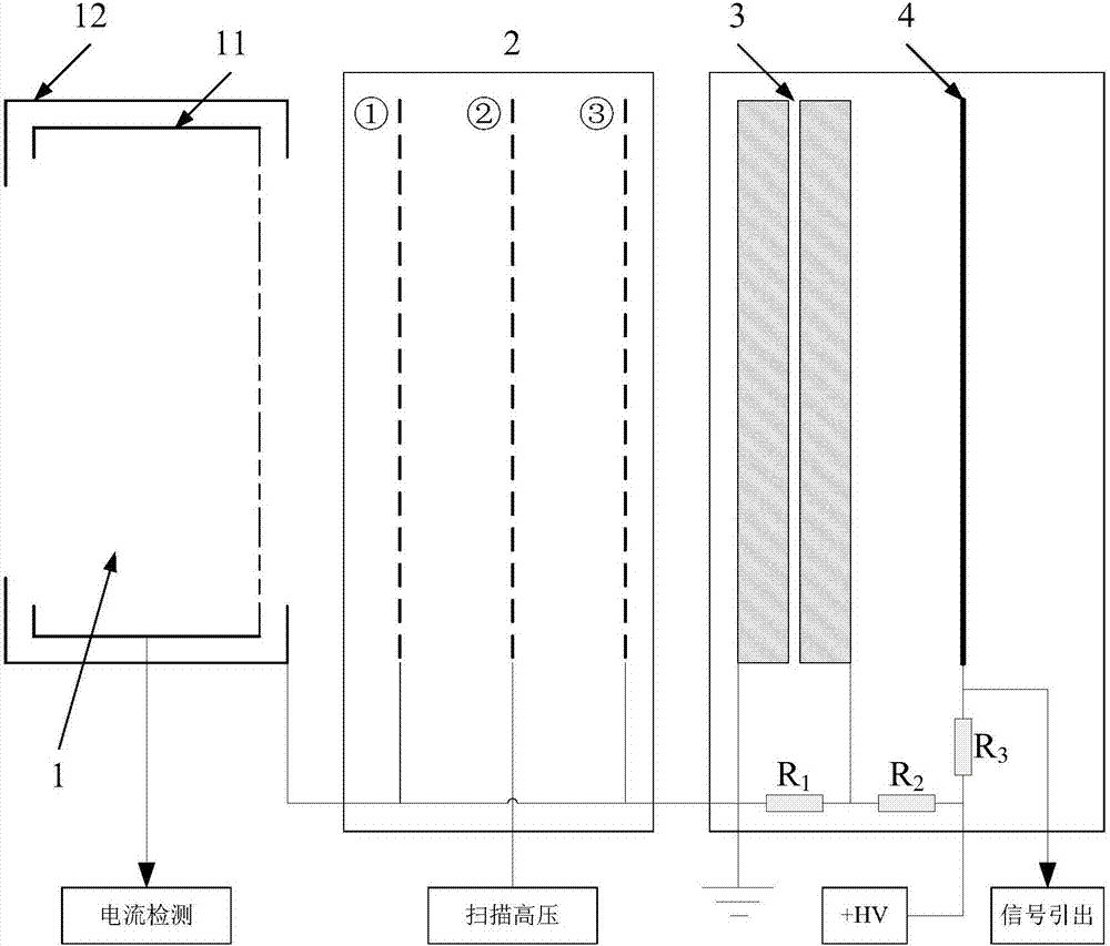
[0034] The object of the present invention is to provide a charged particle beam diagnostic device and related diagnostic measurement method for space environment simulation test. Commonly used spatial low-energy charged particle simulation sources have an energy range of 0.1-80keV and a flow range of 10-1010cm -2 the s -1 , the beam spot size is ≥50mm, and the beam divergence angle is ≤±2°. It is difficult for traditional Faraday cup 1 and MCP detectors to meet such a large dynamic range of energy and flux and charged particle beam diagnosis of beam cross section.

[0035] MCP microchannel plate 3 is a large-area electron multiplication device. It uses the characteristics of secondary electron emission to multiply the secondary electrons generated by high-speed impact, and finally achieve a thousand-fold increase in electron flow. It is an ideal diagnos...


PUM


Abstract

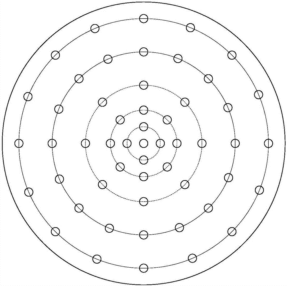
The invention discloses a charged particle beam diagnosis device and a diagnosis measurement method. Through organic combination of a Faraday cylinder, a grid electrode and an MCP detection system, diagnosis of large-dynamic-range charged particle beam source parameters is realized, and simultaneous measurement of energy spectrum, absolute flow, collimation and uniformity of charged particles is also realized; through the design of three layers of parallel grids, energy of the charged particles can be selected by changing the voltage of the intermediate grid, the grids at the two ends are grounded to enable a uniform acceleration and deceleration electric field to be formed between the grids, and since the grids at the two ends can realize effective shielding for the changing electric field, magnetic characteristics of other devices are not influenced; and through design of small holes in the inner cylinder bottom portion of Faraday cylinder, measurement influence on absolute beam intensity is very small, beam intensity is greatly reduced, and counting measurement carried out by a follow-up MCP detection system for the charged particles can be realized conveniently.

Description

technical field [0001] The invention belongs to the technical fields of aerospace and precision optomechanical, and in particular relates to a charged particle beam diagnostic device and a diagnostic measurement method suitable for space charged particle environment simulation and diagnosis of various charged particle beam sources. Background technique [0002] In the measurement of X-ray photons for the purpose of spatial positioning, the measurement and counting of X-ray photons radiated by a certain pulsar, in addition to the photon counts from the pulsar source, also includes radiation from all directions in the detector's field of view The additional count of entering the field of view, this additional count from non-pulsar sources in space is called background noise. During the pulsar navigation process, the space charged particles in the background noise will also be mixed in the pulsar radiation X-ray signal, which will interfere with the photon count received by the...

Claims


Application Information

Patent Timeline
Patent Type & Authority Applications(China)
IPC IPC(8): G01T1/29G01T1/36G01T1/38
Inventor 史钰峰赵小利邵思霈胡慧君孙书坤
Owner SHANDONG INST OF AEROSPACE ELECTRONICS TECH
Learn More