
UAV collaboration SLAM method based on visible light visual communication

A technology for visual communication and unmanned aerial vehicles, applied in the field of unmanned aerial vehicles, can solve the problems of decreased light-dark contrast ratio, optical coordination signal transmission errors, communication failures, etc., to improve the communication rate and response rate, enhance the synergy effect, and ensure confidentiality. sexual effect

Active Publication Date: 2017-12-08
FOSHAN NANHAI GUANGDONG TECH UNIV CNC EQUIP COOP INNOVATION INST +1
View PDF6 Cites 6 Cited by
  • Summary
  • Abstract
  • Description
  • Claims
  • Application Information

AI Technical Summary

Problems solved by technology

But in the process of using light as visual communication, the biggest problem is: when using the camera to take pictures or take pictures, there is a problem that the brightness of the center point of the LED is too high, which will cause the saturation and overflow of the pixel electrons at the position, and cause some dark stripes to become darker. In the actual process of optical cooperative communication, if the image stripes are not processed, it is easy to cause errors in the transmission of optical cooperative signals, and eventually lead to communication failure.
In this plan, although it is disclosed that the communication method between the auxiliary UAV and the main UAV is to rely on the image information collected by the onboard camera, it does not disclose the communication method between the main UAV and the auxiliary UAV. There is no specific way of information coordination between the auxiliary UAV and the main UAV.

Method used


Image

  • UAV collaboration SLAM method based on visible light visual communication
  • UAV collaboration SLAM method based on visible light visual communication
  • UAV collaboration SLAM method based on visible light visual communication

Examples


Embodiment

[0051] Embodiment: A method for UAV cooperative SLAM based on visible light visual communication.

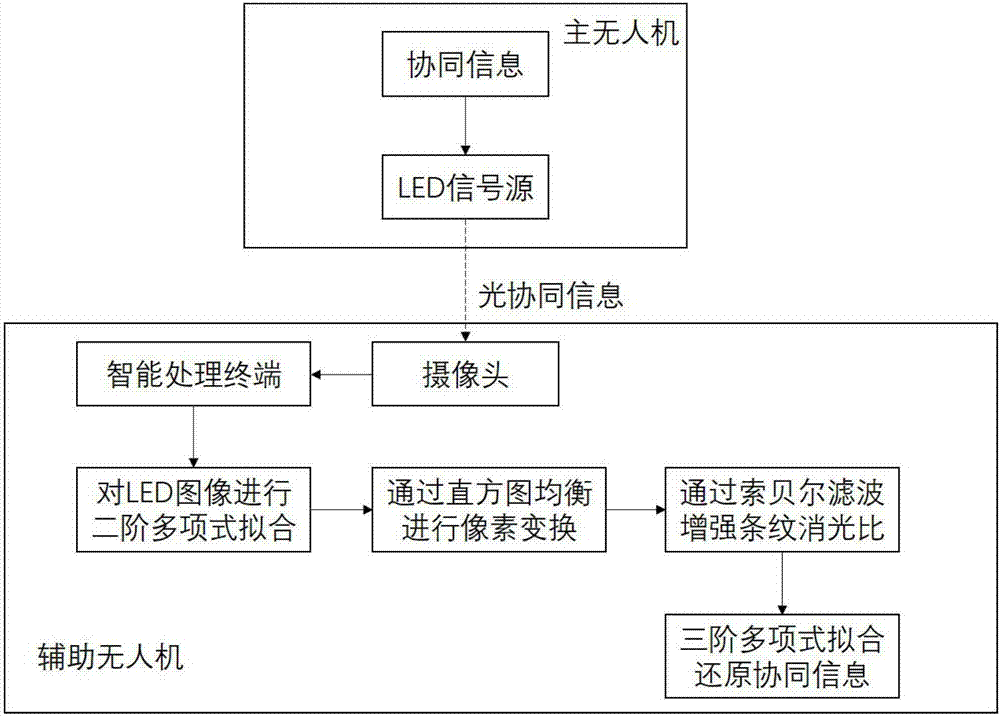
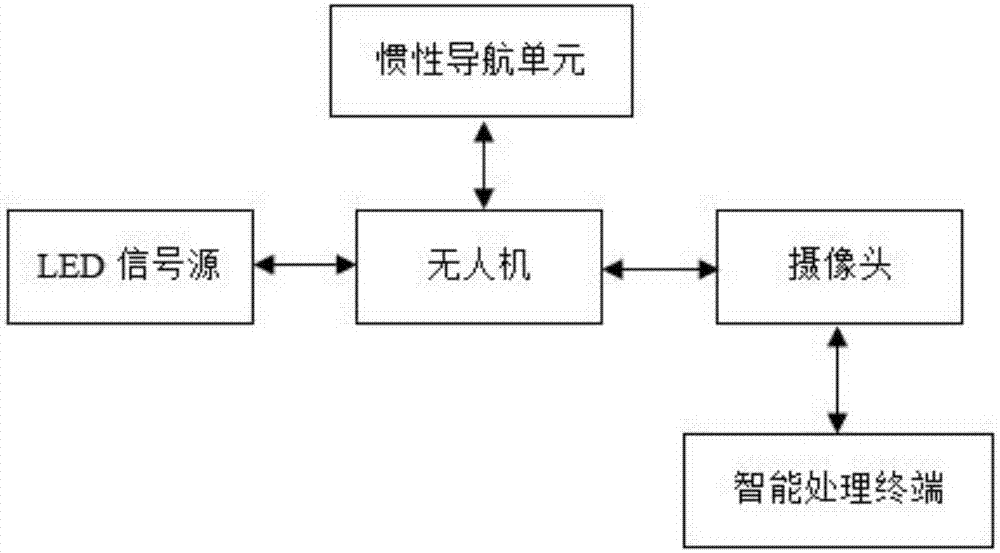
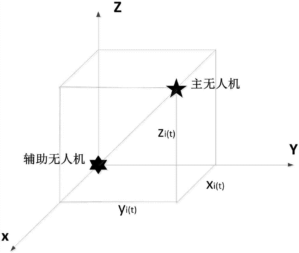
[0052] A method of UAV cooperative SLAM based on visible light communication, such as figure 2 As shown, in this method, one main UAV and four auxiliary UAVs are specifically involved. LED signal sources, CMOS cameras, inertial navigation units and intelligent processing terminals are all installed on the main UAV and the auxiliary UAVs, wherein The inertial navigation unit is used to obtain its own attitude angle, acceleration and other information, and calculate its own position under the earth coordinates; the LED signal source transmits cooperative information through high-frequency flickering; the camera uses the CMOS shutter effect to obtain the cooperative information sent by the LED, and performs Optical communication; the intelligent processing terminal is used to process the image signal received by the camera; and obtain the location information to complete the SLAM ...


PUM


Abstract

The invention provides a UAV collaboration SLAM method based on visible light visual communication. The method comprises collecting a LED signal light source twinkling at a high frequency on a master UAV by using a CMOS camera on an auxiliary UAV, and converting an optical signal into a digital signal, eliminating a defect that it is possible to unclearly differentiate between dark stripes and bright stripes because of the saturation overflow of pixel electrons in a high-frequency flicker imaging process so as to ensure information coordination of the master UAV and the auxiliary UAV, to achieve the lighting and the communication simultaneously, and to improve the communication rate and the reaction rate between the master UAV and the auxiliary UAV, thereby enhancing a coordination effect between the master UAV and the auxiliary UAV. Furthermore, the visible range of visibility communication mode of visible light can ensure information confidentiality, prevent the information from being monitored, cannot generate electromagnetic interference, and is suitable for confidential or electromagnetically sensitive applications.

Description

technical field [0001] The invention relates to the technical field of unmanned aerial vehicles, in particular to a method for cooperative SLAM of unmanned aerial vehicles based on visible light visual communication. Background technique [0002] UAVs are now widely used in many fields such as military and civilian use. In the military, unmanned aerial vehicles can complete tasks such as air early warning, reconnaissance and surveillance, communication relay and small-scale attacks. In terms of civilian use, UAVs can complete tasks such as environmental monitoring, remote sensing detection, search and rescue in disaster areas, and pesticide spraying. The confirmation of the position of the UAV is the basis of safe flight. At present, the main positioning method of the UAV is GPS positioning, and the GPS wireless communication system will be affected by electromagnetic interference. In buildings, densely populated cities, under bridges, underground and other environments, d...

Claims


Application Information

Patent Timeline
Patent Type & Authority Applications(China)
IPC IPC(8): H04B10/116H04B10/69G05D1/10
CPCG05D1/101H04B10/116H04B10/695
Inventor 陈颖聪
Owner FOSHAN NANHAI GUANGDONG TECH UNIV CNC EQUIP COOP INNOVATION INST
Learn More