Micro-channel integrated cold plate based on a micro-channel porous flat tube and making method thereof

A micro-channel and flat-tube technology, applied in electrical components, electrical solid devices, circuits, etc., can solve the problems of leakage and heat conduction, affecting sealing, poor and other problems, and achieve the effect of matching expansion coefficient and reducing thermal resistance.

Inactive Publication Date: 2017-12-12
SOUTHWEST CHINA RES INST OF ELECTRONICS EQUIP
View PDF3 Cites 14 Cited by
  • Summary
  • Abstract
  • Description
  • Claims
  • Application Information

AI Technical Summary

Problems solved by technology

This method has a high processing maturity for large-scale liquid-cooled channel cold plates, but for micro-channel liquid-cooled plates, there are the following problems: too much solder leads to channel blockage, too little solder affects sealing, and fins during machining It is easy to bend and deform, and the thickness of the cover plate should not be too thin, etc., which affects the maturity of this conventional method on the microch

Method used


Image

  • Micro-channel integrated cold plate based on a micro-channel porous flat tube and making method thereof
  • Micro-channel integrated cold plate based on a micro-channel porous flat tube and making method thereof
  • Micro-channel integrated cold plate based on a micro-channel porous flat tube and making method thereof

Examples


specific Embodiment

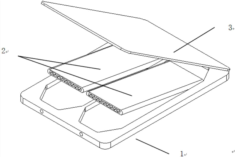
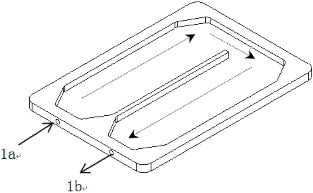
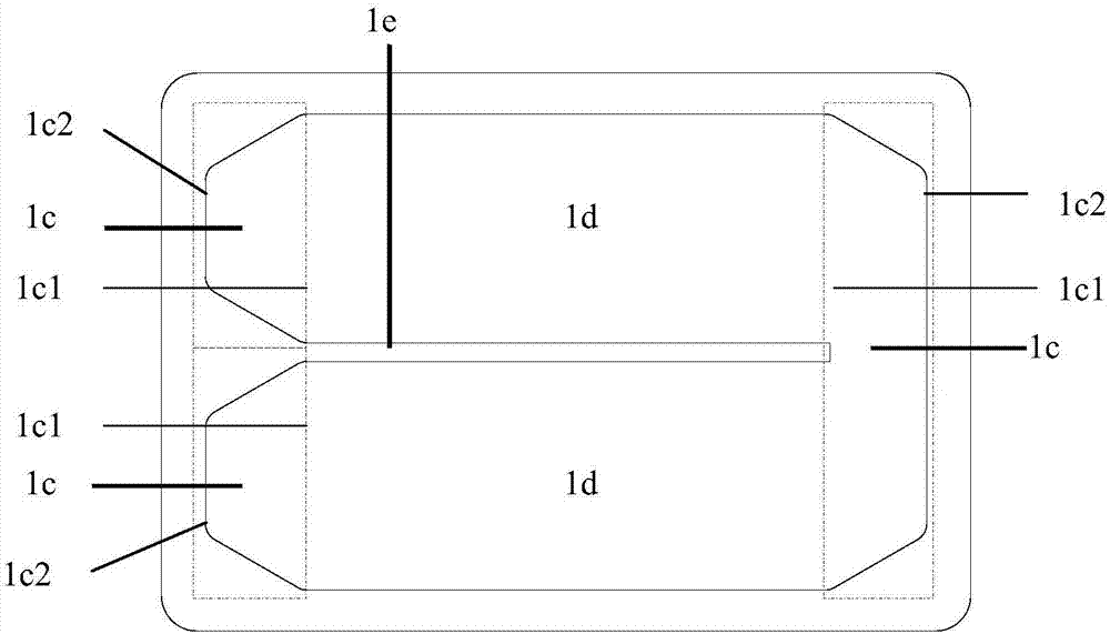
[0054] Specific embodiment: Based on the present invention, a liquid-cooled heat dissipation component is processed, and the liquid-cooled micro-channel flat tube is embedded in the bottom plate of the box body to realize rapid prototyping and welding. At the same time, the matching of the thermal expansion coefficient of the chip and the cold plate is taken into account, and the expectation is achieved. cooling effect. Specific implementation examples such as Figure 8 : In this example, the bottom plate of the box body is used as the base plate and structural support of the cold plate at the same time. Mounting ears are arranged on the outside of the box body for external connection of the box body. The outer dimension of the box body is 46mm*31mm*7mm. The inside of the box body is processed with a flow channel cavity and a confluence cavity, and the flow channel cavity is embedded with two porous flat tubes arranged in series. The flat tube is 21mm long and 13mm wide, with...


PUM


Abstract

The invention relates to the field of an equipment heat dissipation technology, in particular to a micro-channel integrated cold plate based on a micro-channel porous flat tube and a making method thereof. The micro-channel integrated cold plate comprises a cavity area used for accommodating the micro-channel porous flat tube, a liquid-cooled cavity substrate used for accommodating the cavity area and a cover plate used for covering the liquid-cooled cavity substrate to form a closed structure; the cavity area is formed by two confluence cavities with a gradual change in shape and a flow channel cavity; the confluence cavity in the head part of the cavity area, the flow channel cavity and the confluence cavity in the tail part of the cavity area are sequentially connected; the end part of the flow channel cavity formed close to a cold plate liquid inlet and a cold plate liquid outlet is matched with the size of the flaring end of each of the confluence cavities; cooling liquid sequentially passes through the cold plate liquid inlet and outlet, the confluence cavity converging end, the confluence cavity flaring end, the flow channel cavity, the confluence cavity flaring end, the confluence cavity converging end and the cooling liquid outlet; the micro-channel porous flat tube is hermetically welded in the flow channel cavity of the liquid-cooled cavity substrate, and the cold plate liquid inlet and the cold plate liquid outlet are formed in the front end or the rear end of the liquid-cooled cavity substrate.

Description

technical field [0001] The invention relates to the technical field of heat dissipation of electronic equipment, in particular to a microchannel integrated cold plate based on a microchannel porous flat tube and a manufacturing method thereof. Background technique [0002] Liquid cooling is a common cooling method for high-heating electronic chips in the electronics industry. The principle is to set up a liquid cooling channel inside the electronic chip mounting plate (also known as a cold plate), through which the cooling liquid is introduced, and the cooling liquid is used to take away the heat generated by the electronic chip, thereby cooling down the electronic chip. [0003] An effective way to improve the heat dissipation efficiency of liquid cooling is to increase the heat transfer area within a limited volume as much as possible, that is, arrange as many liquid cooling channels as possible in the cold plate (make the size of a single channel as small as possible, rea...

Claims


Application Information

Patent Timeline
IPC IPC(8): H01L23/367H01L23/473
CPCH01L23/367H01L23/473
Inventor 祁成武赵艳尹本浩
Owner SOUTHWEST CHINA RES INST OF ELECTRONICS EQUIP
Why Eureka
Try Eureka