
Liquid metal heat-conduction filling material-containing polyethylene terephthalate heat-conduction film

A technology of thermally conductive film and thermally conductive filler, applied in the direction of film/sheet adhesive, adhesive type, adhesive additive, etc. Lifting and falling, the coating effect is not ideal, etc., to achieve good adhesive effect, good thermal conductivity effect, and the effect of not easy to separate

Active Publication Date: 2017-12-19
深圳沃尔提莫电子材料有限公司
View PDF4 Cites 11 Cited by
  • Summary
  • Abstract
  • Description
  • Claims
  • Application Information

AI Technical Summary

Problems solved by technology

[0006] At present, for the application technology of liquid metal as a heat-conducting material, one is to directly disperse the liquid metal in the polymer matrix, but because the van der Waals force between the liquid metal is very large, the droplets dispersed in the polymer matrix are relatively large, and The size uniformity is poor, and the bonding between the metal droplet and the polymer matrix is ​​poor, and the interface difference makes the thermal conductivity of the entire thermal conductivity material not increase but decrease; there is another method to try to use the solidified metal powder and process it Surface coating, and then disperse the coated metal powder in the polymer matrix as a thermally conductive material, but due to the low melting point of liquid metal, the operation of metal particles and coating needs to be carried out at low temperature, and the operating conditions are harsh And the coating effect is not ideal
In addition, the existing technical means are to disperse the liquid metal in the whole polymer matrix, and exist as a specific heat-conducting material (heat-conducting patch), and cannot exist as an independent heat-conducting filler, which greatly limits the liquid metal as a Breadth and depth of applications for thermally conductive materials

Method used


Image

  • Liquid metal heat-conduction filling material-containing polyethylene terephthalate heat-conduction film
  • Liquid metal heat-conduction filling material-containing polyethylene terephthalate heat-conduction film
  • Liquid metal heat-conduction filling material-containing polyethylene terephthalate heat-conduction film

Examples


Embodiment Construction

[0043]The invention will be further described below. For the convenience of description, the equipment in the present invention omits necessary or conventional operation steps or conditions, and those skilled in the art can make arbitrary adjustments according to the needs of the reaction. Under the condition of no conflict, the features of the various embodiments in the solution of the present invention can be combined with each other.

[0044] 1. Preparation of materials

[0045] All raw materials of the present invention are commercially available or obtained by conventional methods. The following commercially available or self-made raw materials (preparation methods are conventional methods) are adopted in the examples of this case:

[0046] Low melting point metals or alloys (commercially available): indium gallium alloy: melting point 12°C; indium gallium tin alloy: melting point 10°C;

[0047] Side chain carboxyl-containing polysiloxane (self-made): add octamethylcyc...


PUM

PropertyMeasurementUnit
melting pointaaaaaaaaaa

Abstract

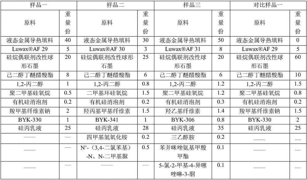
The invention provides a PET (polyethylene terephthalate) heat-conduction film, which comprises a PET bearing membrane and an adhesive material layer attached on the surface of the PET bearing membrane. The adhesive material layer comprises the following raw materials by weight: 10-50 parts of a liquid metal heat-conduction filling material, 2-10 parts of micro wax powder, 20-30 parts of spherical graphite, 1-10 parts of a membrane-forming auxiliary agent, 0.5-3 parts of a cosolvent, 0.5-3 parts of a dispersant, 0.1-0.5 parts of an antifoaming agent, 0.1-2 parts of a thickening agent, 0.1-2 parts of a levelling agent, 20-40 parts of a silicone acrylic emulsion, and 0-5 parts of other auxiliary agents. The heat-conduction film has high heat conduction coefficient, and the adhesive material has stable long-term coating and stripping effects on the PET membrane.

Description

technical field [0001] The invention relates to the technical field of heat-dissipating films, in particular to a PET heat-conducting film containing liquid metal heat-conducting fillers, which is used in the same way as ordinary PET double-sided or single-sided adhesives. Background technique [0002] PET double-sided adhesive tape or single-sided adhesive tape is made of PET double-sided or single-sided coated adhesive material containing heat dissipation medium. Various bonding applications in electronic products. [0003] Since PET double-sided tape or single-sided tape uses PET as a carrier, it is required that the adhesive material has a long-term stable coating and peeling effect on the PET film, and has good thermal conductivity. [0004] At present, the most studied is to use C materials such as graphite and carbon nanotubes as thermally conductive fillers, but the amount of C materials dispersed in the adhesive matrix is ​​limited, and the thermal conductivity is ...

Claims


Application Information

Patent Timeline
Patent Type & Authority Applications(China)
IPC IPC(8): C09J7/02C09J133/04C09J11/04
CPCC09J11/04C09J143/04C08L2205/035C08K2201/014C09J2301/30C09J2301/122C09J2301/408C08L83/04C08K13/06C08K9/10C08K9/06C08K3/08
Inventor 何千舟李雲张耀湘
Owner 深圳沃尔提莫电子材料有限公司
Learn More