Ozone bleaching device

An ozone and central pipe technology is applied in pulp bleaching, preventing corrosion/sediment formation of pulping equipment, and papermaking. Effect

Active Publication Date: 2017-12-19
KUNMING UNIV OF SCI & TECH
View PDF6 Cites 0 Cited by
  • Summary
  • Abstract
  • Description
  • Claims
  • Application Information

AI Technical Summary

Problems solved by technology

[0004] The object of the present invention is to provide an ozone bleaching device that can monitor pulp concentration in real time, which solves the problems of trivial process and low bleaching efficiency in the industrial application of ozone bleaching. The device has simple structure, strong operability, and can control pulp Concentration greatly simplifies the process flow, reduces production costs, and can achieve better bleaching effect, providing a scientific basis for the economy, high efficiency, energy saving and consumption reduction of ozone bleaching

Method used


Image

  • Ozone bleaching device
  • Ozone bleaching device
  • Ozone bleaching device

Examples


Embodiment 1

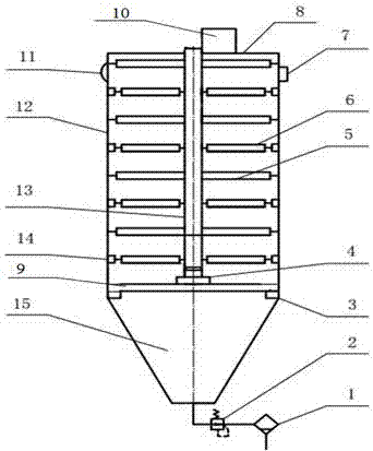
[0029] Embodiment 1: as Figure 1-5As shown, the ozone bleaching device of the present invention includes a slurry discharger 1, a pressure regulating valve 2, an annular bearing platform 3, a motor I4, a central pipe branch 5, a pulp-hanging omentum 6, a liquid level sensor 7, a constant pressure pump 10, an infrared moisture Instrument 11, box body 12, center pipe 13, motor II 14, slurry conical pool 15, universal coupling 18; the box body 12 includes a sealed box cover 8, a box bottom 9, and the box bottom 9 is provided with a leak hole. The diameter of the hole is 4 mm, and the annular bearing platform 3 is installed under the box bottom 9, and the slurry accumulation conical pool 15 is installed under the annular bearing platform 3. Regulating valve 2, motor I4 is installed above the box bottom 9, one end of the central tube 13 is connected to the output shaft of the motor I4, the motor I4 drives the central tube 13 to rotate, the other end of the central tube 13 protrude...

Embodiment 2

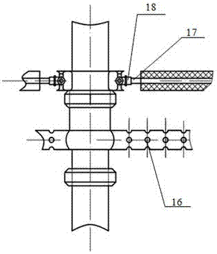
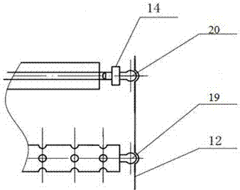
[0030] Embodiment 2: The device structure of this embodiment is the same as that of Embodiment 1. The difference is that the diameter of the 9 leakage holes at the bottom of the box is 2mm, and there are 6 layers of slurry-coating layers on the central tube 13, and each layer has 8 slurry-coating omentums, which have 6 layers. There are 16 central pipe branching layers in each layer. The diameter of the holes on the central pipe branching pipes 5 is 3cm, and the interval along the axis is 10cm. The diameter of lubricating ball I19 and lubricating ball II20 is 5cm. The vertical distance between the plasma omentum 6 is 15 / 24 of the 6 arc lengths of the slurry omentum.

Embodiment 3

[0031] Embodiment 3: The device structure of this embodiment is the same as that of Embodiment 1. The difference is that the diameter of the 9 leakage holes at the bottom of the box is 5mm, and there are 8 layers of slurry-coating layers on the central tube 13, and each layer has 12 slurry-coating omentums, which have 8 layers. The central tube is divided into layers, and each layer has 18 central tubes 5. The diameter of the holes on the central tube 5 is 2cm, and the distance along the axis is 8cm. The diameter of the lubricating ball I19 and the lubricating ball II20 is 4.5cm.

[0032] The slurry is pumped into the center pipe 13 with a certain pressure through the constant pressure pump 10, and discharged through the center pipe branch pipe 5. Because the pressure is constant, the pressure value of each center pipe branch pipe 5 can be made the same, and the slurry passes through the central pipe branch pipe 5. The hole 16 is discharged, evenly sprinkled on the slurry oment...


PUM

PropertyMeasurementUnit
diameteraaaaaaaaaa

Abstract

The invention discloses an ozone bleaching device. The ozone bleaching device comprises a pulp draining machine, a pressure adjusting valve, an annular bearing table, a motor I, center pipe branch pipes, pulp hanging net films, a liquid level sensor, a constant pressure pump, an infrared moisture meter, a box body, a center pipe, a motor II, a pulp accumulating conical pond, and a universal shaft coupler. The ozone bleaching device disclosed by the invention integrates technologies of pulp hanging, pulp dehydrating, ozone bleaching, pulp washing and the like, so that technological processes are greatly shortened, and the production cost is reduced; the ozone bleaching device is simple in structure, high in operability, and good in bleaching effect; and through the adoption of the ozone bleaching device disclosed by the invention, the pulp with the maximum surface area can be obtained, and the pulp can be in sufficient contact with ozone, so that the bleaching efficiency is improved; and the ozone bleaching device disclosed by the invention is simple, economical, high-efficiency and energy-saving.

Description

technical field [0001] The invention belongs to the technical field of pulping and papermaking, and in particular relates to an efficient ozone bleaching device. Background technique [0002] With the improvement of environmental laws and regulations and the improvement of people's awareness of environmental protection, the pollution caused by the traditional bleaching process of pulp and papermaking has attracted more and more attention and attention from the society. Therefore, it is urgent to adopt new bleaching agents to replace traditional chlorine-containing bleaching agents. In recent years, both production practice and theoretical research are more inclined to use oxygen-containing bleaching agents in the non-chlorine bleaching series, and great expectations have been placed on them. No carcinogens are produced in the oxygen-containing bleaching agent wastewater, and the most important thing is that the pollution load brought by the waste liquid to the environment i...

Claims


Application Information

Patent Timeline
Patent Type & Authority Applications(China)
IPC IPC(8): D21C9/10D21C9/18D21C9/00
CPCD21C9/008D21C9/1047D21C9/1073D21C9/18
Inventor 张立龙邵思成陈克利袁海阔
Owner KUNMING UNIV OF SCI & TECH
Why Eureka
Try Eureka