Integrated device for dredging drainage pipeline based on high pressure rotating jet flow

A drainage pipeline and high-pressure technology, applied in the field of drainage pipeline dredging equipment, can solve the problems of waste of water resources, high risk and easy occurrence of poisoning, and achieve the effects of saving water resources, improving dredging efficiency and good dredging effect.

Pending Publication Date: 2017-12-19
SHANGHAI WATER ENG DESIGN & RES INST
View PDF4 Cites 12 Cited by
  • Summary
  • Abstract
  • Description
  • Claims
  • Application Information

AI Technical Summary

Problems solved by technology

This method is economical and economical to operate, but it needs to manually go down the well to complete the transportation of TT sheets between the pits, which may cause safety accidents due to the harsh working environment underground; 2. Manual dredging method, this method requires a group of "underground workers" , they shuttled back and forth through the foul-smelling drains, the porters of the silt in the drains
However, this method is extremely dangerous, because toxic and harmful gases such as hydrogen sulfide, ammonia, sulfur dioxide, and carbon monoxide will be precipitated in the sewage, which is prone to poisoning or explosion accidents in case of open flames, and there are disadvantages such as small-caliber pipelines that are difficult to clean ;3. Hydraulic flushing method, which uses the water flow formed by the upstream water s

Method used


Image

  • Integrated device for dredging drainage pipeline based on high pressure rotating jet flow
  • Integrated device for dredging drainage pipeline based on high pressure rotating jet flow
  • Integrated device for dredging drainage pipeline based on high pressure rotating jet flow

Examples


Embodiment Construction

[0026] In order to make the technical means, creative features, goals and effects achieved by the present invention easy to understand, the present invention will be further described below in conjunction with specific illustrations.

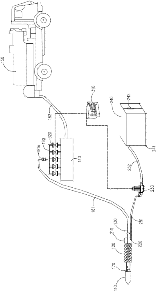
[0027] Referring to the accompanying drawings, the figure shows an integrated drainage pipe dredging device based on high-pressure rotary jet, including a flushing component, a dredging component and a control component.

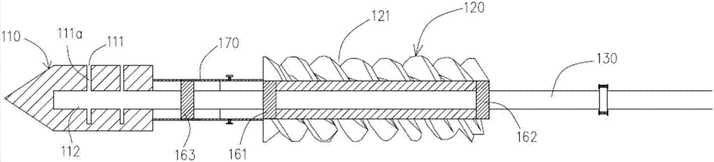
[0028] The flushing assembly includes a high-pressure nozzle 110 , a helical sleeve rod 120 , a hollow steel pipe 130 , a pressurized gas tank 140 and a dredging vehicle 150 .

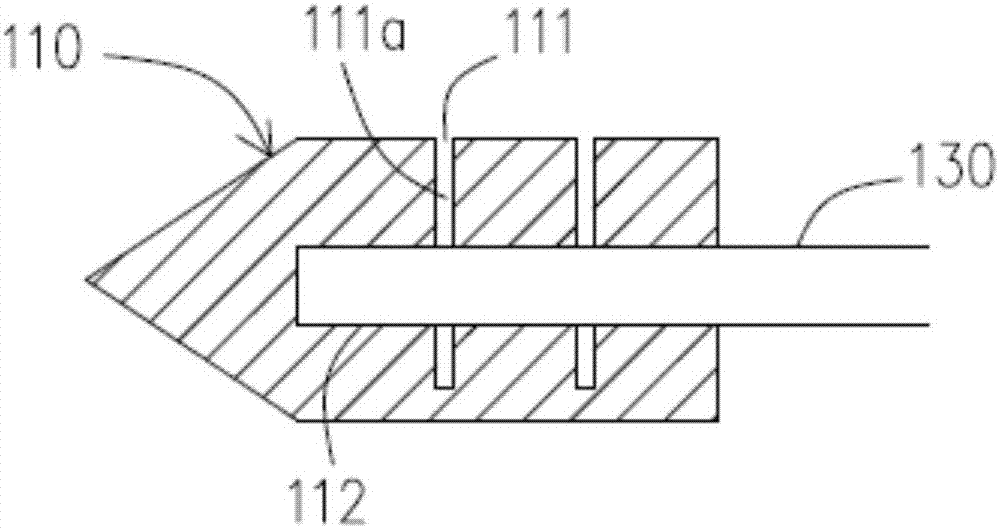
[0029] The high-pressure nozzle 110 is axially arranged on the first end of the hollow steel pipe 130 and its water inlet end is connected to the first port 131 of the hollow steel pipe 130 . The outer surface of the high-pressure nozzle 110 is provided with several spray holes 111 at intervals in the upper direction. In this embodiment, the front part...


PUM


Abstract

The invention discloses an integrated device for dredging a drainage pipeline based on high pressure rotating jet flow. The device is composed of three parts, namely, a control assembly, a washing assembly and a dredging assembly, wherein a magnetic valve and a central control unit in the control assembly are connected through necessary signal lines. A hollow stainless steel tube is sleeved with a high pressure nozzle and a screw rod in the washing assembly and fixed through a fixing support on a bearing, and the hollow stainless steel tube is connected to a high pressure rubber tube on a dredge car. A mud blocking trough in the dredging assembly is installed on the hollow stainless steel tube, and a sucker is installed in the mud blocking trough and connected to a mud sucking pipe which is connected with a mud storage trough through a mud pump. Compared with a traditional method for cleaning silt in a drainage pipeline, the integrated device has the advantages of being safer, more efficient and water-saving, the water flow of jet grouting can crush sediments and obstacles which are deposited at the bottom of the drainage pipeline, and the screw rod is used to stir fully; therefore, the purpose of complete dredging is achieved, and the integrated device is an effective silt cleaning device.

Description

technical field [0001] The invention relates to the technical field of desilting equipment for drainage pipes, in particular to an integrated device for desilting drainage pipes based on high-pressure rotating jets. Background technique [0002] With the continuous acceleration of the urbanization process, the urban population has increased rapidly, the water consumption of residents has continued to increase, and the drainage volume has increased accordingly. When residents discharge domestic sewage into the drainage pipes, some domestic garbage is often entrained. At the same time, the rain and sewage confluence system was adopted in the early construction of drainage pipelines. During the process of urban heavy rain, silt, domestic garbage and construction waste entered the drainage system under the washing of rainwater. Drainage capacity is reduced and clogging may occur. [0003] At present, there are many ways to clean up the sediment in the drainage pipe: 1. Slow car...

Claims


Application Information

Patent Timeline
IPC IPC(8): E03F9/00
CPCE03F9/002
Inventor 申屠华斌
Owner SHANGHAI WATER ENG DESIGN & RES INST
Why Eureka
Try Eureka