Graphene electrode dielectric elastomer driver

A dielectric elastomer, graphene electrode technology, applied in generators/motors, piezoelectric effect/electrostrictive or magnetostrictive motors, electrical components, etc., to achieve excellent performance indicators, overall performance improvement, electrical conversion Efficient effect

Pending Publication Date: 2017-12-19
CHINA UNIV OF GEOSCIENCES (WUHAN)
View PDF7 Cites 13 Cited by
  • Summary
  • Abstract
  • Description
  • Claims
  • Application Information

AI Technical Summary

Problems solved by technology

[0003] Aiming at the series of problems existing in the current driver, the present invention provides a graphene electrode dielectric elastomer driver to optimize and improve the comprehensive performance of the driver

Method used


Image

  • Graphene electrode dielectric elastomer driver
  • Graphene electrode dielectric elastomer driver
  • Graphene electrode dielectric elastomer driver

Examples


Embodiment 1

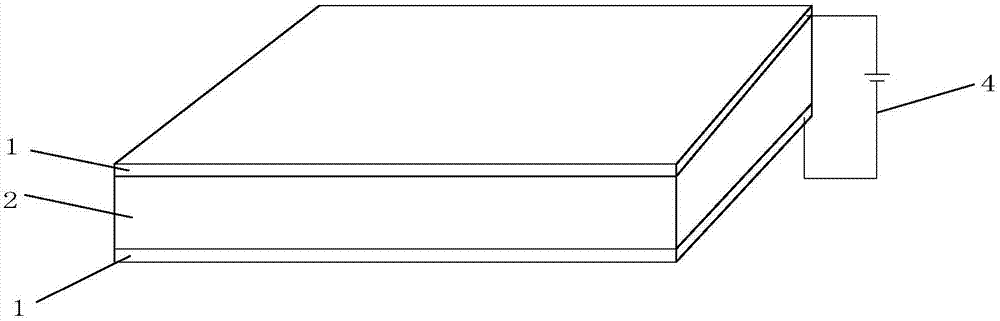
[0029] figure 1 It is the working structure diagram of the graphene electrode single-layer dielectric elastomer driver. The upper and lower sides of the single-layer dielectric elastomer 2 are respectively provided with graphene electrodes 1, forming a sandwich-structured graphene electrode single-layer dielectric. Elastomer driver; the two graphene electrodes 1 are respectively connected to the positive and negative poles of the power supply 4; the graphene electrode 1 is made of graphene film material, and the single-layer dielectric elastomer 2 is made of acrylate elastomer material . The single-layer dielectric elastomer 2 is located between the two graphene electrodes 1, when a voltage is applied on the graphene electrodes 1 on both sides, the static electricity generated between the two graphene electrodes 1 Attraction produces extrusion force in the thickness direction of the single-layer dielectric elastomer 2, which can cause the single-layer dielectric elastomer 2 t...

Embodiment 2

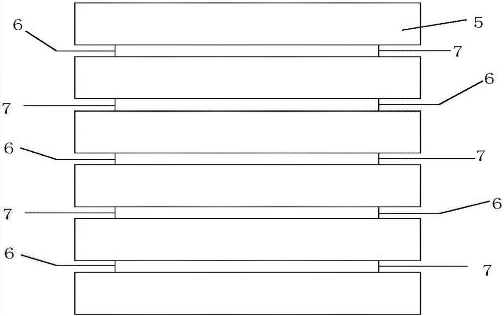
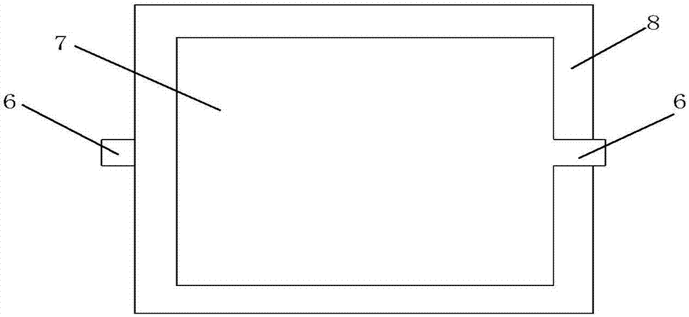
[0031] figure 2 It is a schematic cross-sectional diagram of the structure of a graphene electrode rectangular stacked dielectric elastomer driver; image 3 It is a schematic diagram of the structure of the graphene electrode rectangular stacked dielectric elastomer driver unit; the graphene electrode rectangular stacked dielectric elastomer driver is composed of graphene electrode rectangular single-layer dielectric elastomer units stacked in sequence; the graphene electrode includes: rectangular graphite Graphene layer 7, lead-out electrode 6; Both sides of the rectangular dielectric elastomer 5 in the graphene electrode rectangular single-layer dielectric elastomer unit all have described rectangular graphene layer 7; On both sides of described rectangular graphene layer 7 Both sides have said lead-out electrode 6 (see figure 2 , image 3 ); There are small insulating frame regions 8 (see image 3 ) to prevent short circuit between graphene electrodes. The rectangular...

Embodiment 3

[0034] Figure 4 It is a schematic diagram of the structure of a graphene electrode circular stack type dielectric elastomer driver; Figure 5It is a schematic diagram of the unit structure of the graphene electrode circular stack type dielectric elastomer driver; the graphene electrode circular stack type dielectric elastomer driver is composed of graphene electrode circular single-layer dielectric elastomer units stacked in sequence; Including: circular graphene layer 9, extraction electrode 10 (see Figure 4 , Figure 5 ); the two sides of the dielectric elastomer in the graphene electrode circular single-layer dielectric elastomer unit all have described circular graphene layer 9; All have described circular graphene layer 9 on both sides Lead-out electrode 10; There are small insulating frame regions 11 (see Figure 4 , Figure 5 ), to prevent short-circuit phenomenon between the circular graphene layers 9. The circular graphene layer 9 adopts a graphene composite ma...


PUM


Abstract

The invention relates to a graphene electrode dielectric elastomer driver. Graphene electrodes are arranged on the two side surfaces of the dielectric elastomer to form a sandwich structure, and a graphene electrode dielectric elastomer thickness displacement driver and a graphene electrode dielectric elastomer plane displacement driver are obtained by deformation in different directions; each graphene electrode comprises a graphene layer and an extraction electrode; the graphene layer is a graphene thin film, a graphene coating layer or a graphene composite material layer; and the graphene electrode dielectric elastomer driver is a graphene electrode single-layer dielectric elastomer driver, a graphene electrode stacked type dielectric elastomer driver, a graphene electrode tubular dielectric elastomer driver or a graphene electrode roll type dielectric elastomer driver. The graphene electrode dielectric elastomer driver can be widely applied to the fields of a robot, aerospace, a mechanical arm, a joint prosthesis, an automobile, artificial muscle, airship tail vane adjustment, a diaphragm pump, intelligent driving, biological medical treatment and the like.

Description

technical field [0001] The invention belongs to the technical field of robot drivers and industrial automation drivers, and more specifically relates to a graphene electrode dielectric elastomer driver. Background technique [0002] At present, with the continuous development of human production and life, the demand for robot technology continues to increase. In extreme and dangerous engineering environments where humans are not suitable, robots provide great convenience to humans. At present, the commonly used driving forms of robots include: electric motor drive, pneumatic drive, hydraulic drive, etc. These traditional driving methods have problems such as low energy density, large volume, large mass, small output force, low safety factor, poor environmental adaptability, low reliability, and inflexibility. It is difficult to achieve biological In addition, the traditional driving method is generally based on a rigid structure, which is difficult to meet the flexibility ...

Claims


Application Information

Patent Timeline
IPC IPC(8): H02N2/00H02N2/06
CPCH02N2/001H02N2/062
Inventor 袁曦明袁一楠
Owner CHINA UNIV OF GEOSCIENCES (WUHAN)
Why Eureka
Try Eureka