Fully-automatic control road marking machine
A road marking and component technology, applied in the field of automatic control of road marking machines, can solve problems such as poor mixing uniformity of paint, and achieve the effects of promoting uniform mixing, improving paint quality and improving transmission efficiency
- Summary
- Abstract
- Description
- Claims
- Application Information
AI Technical Summary
Problems solved by technology
Method used
Image
Examples
Embodiment 1
[0035] Embodiments of the present invention are described in detail below, examples of which are shown in the drawings, wherein the same or similar reference numerals designate the same or similar elements or elements having the same or similar functions throughout. The embodiments described below by referring to the figures are exemplary and are intended to explain the present invention and should not be construed as limiting the present invention.
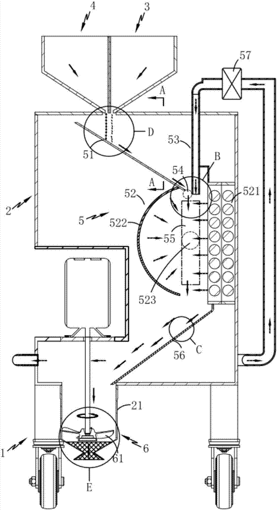
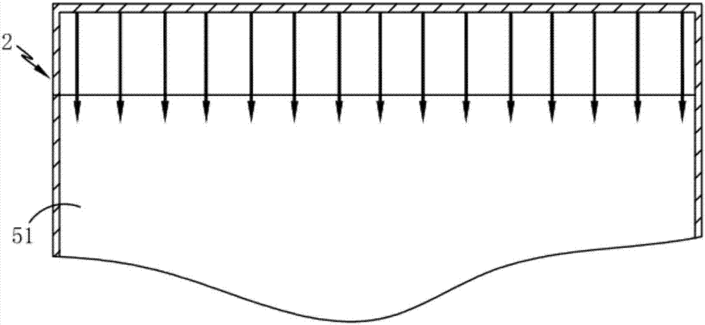
[0036] Such as figure 1 and 2 As shown, the present invention provides a fully automatic control road marking machine, including a bracket 1, a melting bin 2, and a powder bin 3 and a resin bin 4 respectively located on the melting bin 2 and communicating with the interior thereof, and also includes:
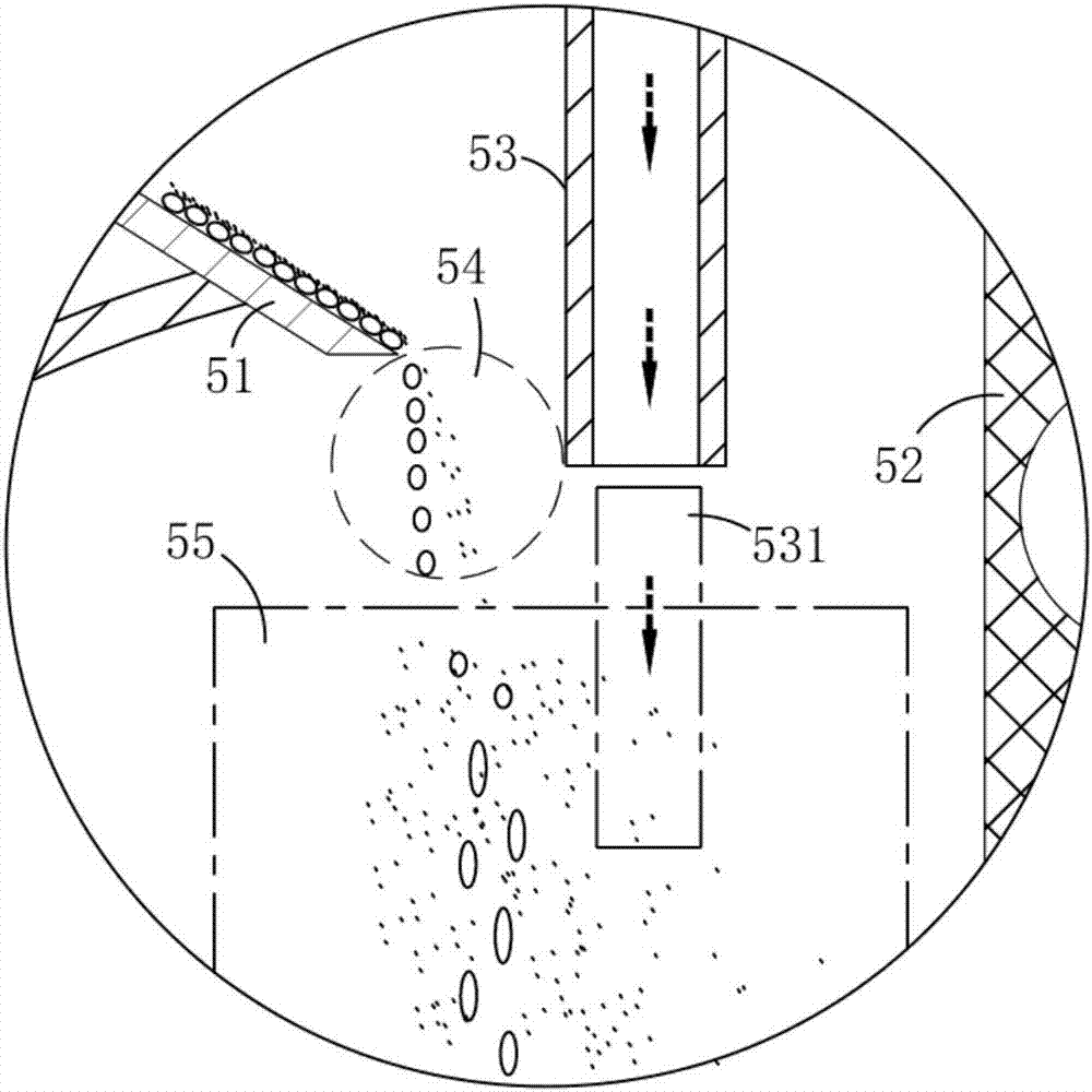
[0037] The melt mixing assembly 5, the melt mixing assembly 5 is arranged inside the melting chamber 2, and it includes a first conveying assembly 51 for transporting the powder material and the resin through the powder chamber 3 ...
Embodiment 2
[0042] Such as figure 1 As shown, the components that are the same as or corresponding to those in Embodiment 1 use the corresponding reference numerals as in Embodiment 1. For the sake of simplicity, only the differences from Embodiment 1 will be described below. The difference between the second embodiment and the first embodiment is that the hot-melt component 52 includes a hot-melt part 521 that liquefies the resin by heat radiation, and a hot-melt part 521 that is arranged below the first transmission component 51 and is connected to the hot-melt The heat-gathering component 522 arranged opposite to the part 521, the heat-gathering component 522 concentrates the heat radiation generated by the hot-melt part 521, and forms a thermal focus area 523 in the melting zone 55, and the heat-gathering component 522 and The hot-melt parts 521 are respectively located on both sides of the melting zone 55. While the heat generated by the hot-melt parts 521 is used to liquefy the mixe...
Embodiment 3
[0045] Such as figure 1 As shown, the parts that are the same as or corresponding to those in Embodiment 2 use the corresponding reference numerals as in Embodiment 2. For the sake of simplicity, only the differences from Embodiment 2 will be described below. The third embodiment is different from the second embodiment in that: the melt mixing assembly 5 also includes an air flow generator 57 communicated with the air flow introduction assembly 53, the air inlet end of the air flow generator 57 is connected to the melting chamber 2 are connected internally, and are located above the spraying chamber 21. The heat in the melting zone is drained to the spraying chamber 21 through the air flow generator 57, and the heat preservation treatment of the coating is carried out, and then the gas with heat is introduced to the spraying chamber 21. Go to the airflow introducing component 53 for preheating treatment of powder and resin.
[0046] It should be noted that, if figure 1 As sh...
PUM
 Abstract
Description
Claims
Application Information
 - R&D
- Intellectual Property
- Life Sciences
- Materials
- Tech Scout
- Unparalleled Data Quality
- Higher Quality Content
- 60% Fewer Hallucinations
Browse by: Latest US Patents, China's latest patents, Technical Efficacy Thesaurus, Application Domain, Technology Topic, Popular Technical Reports.
© 2025 PatSnap. All rights reserved.Legal|Privacy policy|Modern Slavery Act Transparency Statement|Sitemap|About US| Contact US: help@patsnap.com


