Rail fastener abnormity detecting system based on point light source array linear array imaging

An anomaly detection and point light source technology, which is applied to railway car body components, optical test flaws/defects, railway vehicle shape measuring instruments, etc., can solve the problems that are difficult to achieve, high-speed imaging equipment is expensive, and cannot handle the lack of DZⅢ fasteners, etc. problem, achieve the effect of reducing calorific value, small storage and processing capacity, and low cost

Pending Publication Date: 2017-12-22
成都精工华耀科技有限公司
View PDF6 Cites 24 Cited by
  • Summary
  • Abstract
  • Description
  • Claims
  • Application Information

AI Technical Summary

Problems solved by technology

The disadvantages of this type of method are: 1) When using an area array camera to shoot the fastener area, in order to ensure that the rail fasteners are not missed in the images captured by the area array camera, the imaging frequency of the camera should be the frequency of the fasteners appearing during the train running. 2 to 4 times. When the train is running at high speed, for example, when the speed is 300km / h, taking the fastener spacing as 0.5m as an example, and the frequency of fastener appearance is 166Hz, the imaging frame rate of the camera is 332-664fps, which gives the imaging system Image transmission, storage, and processing pose great challenges, and high-speed imaging equipment is expensive; 2) Due to the transmission deformation of area array cameras, in order to ensure that the shooting fasteners have the same image size, an accurate imaging trigger system is required to ensure that the captured images It is located directly above the fastener, which is difficult to achieve when the train is running at high speed; 3) The proposed image processing algorithm is only for the W-shaped spring ( figure 1 (a)) fasteners are valid, but not valid for other types of fasteners, for example: for DZⅢ type fasteners ( figure 1 (b)), the algorithms of the two patents cannot handle the absence of DZⅢ type fasteners ( figure 2 (a)), semi-loose ( figure 2 (b)) and missing gaskets ( figure 2 (c)) problem, so the image processing algorithms of patents 2011100073637.X and 201410667430.9 are not universal

Method used


Image

  • Rail fastener abnormity detecting system based on point light source array linear array imaging
  • Rail fastener abnormity detecting system based on point light source array linear array imaging
  • Rail fastener abnormity detecting system based on point light source array linear array imaging

Examples


Embodiment 1

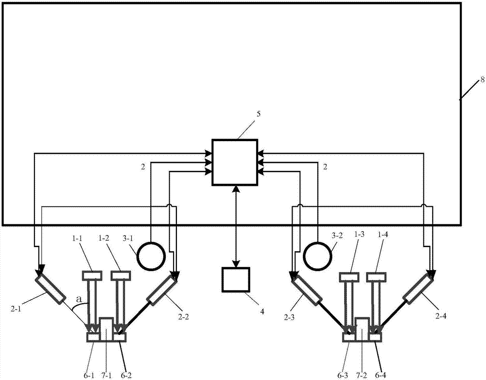
[0033] Such as image 3 As shown, a rail fastener anomaly detection system based on point light source array linear array imaging consists of 4 point light source arrays (1), 4 line array cameras (2), 2 wheel encoders (3-1, 3 -2), an RFID detector (4) and an industrial computer (5).

[0034] Among them, the 4 point light source arrays (1-1, 1-2, 1-3, 1-4) are respectively located directly above the areas of the 4 fasteners (6-1, 6-2, 6-3, 6-4) , the number of circular beams in the point light source array is 10, and the 10 circular beams are arranged in a line at equal intervals, projecting a line-shaped spot array to the fastener area, the plane of the line-shaped light spot is perpendicular to the rail, and the circular beams are at the base of the fastener The diameter of the projection spot is 5mm, and the 4 line scan cameras (2-1, 2-2, 2-3, 2-4) are respectively located on the 4 fasteners (6-1, 6-2, 6-3, 6- 4) obliquely above, the optical axis of the line array camera a...

Embodiment 2

[0049] The difference from Embodiment 1 is that the point light source array 1 uses ten 850nm wavelength narrowband lasers arranged in a line to form a point light source array, and an 850nm narrowband filter is placed at the front end of the line array camera to eliminate ambient light interference.

Embodiment 3

[0051] The difference from Embodiment 2 is that in order to increase the width of the irradiation area of ​​the point light source array, a cylindrical mirror is set at the front end of the circular light beam projected by the point light source array, such as Figure 7 As shown, the circular light beam is modulated into an elliptical spot (11), the major axis of the elliptical spot at the base of the fastener is 20mm, and the minor axis is 1mm.


PUM

PropertyMeasurementUnit
wavelengthaaaaaaaaaa
frame rateaaaaaaaaaa

Abstract

The invention rail fastener abnormity detecting system based on point light source array linear array imaging. The rail fastener abnormity detecting system comprises a point light source array, a linear array camera, a wheel encoder, an RFID detector and an industrial personal computer, wherein the point light source array projects an I-shaped circular light spot to a fastener to modulate the shape and height information of the fastener, the imaging area of the linear array camera penetrates the projection area of the I-shaped circular light spot, the shape modulation light strip image on the surface of the fastener is obtained through scanning, and a deep learning classification method is used to detect abnormities such as fastener elastic rod losing, fastener elastic rod loosening and fastener gasket losing. The rail fastener abnormity detecting system is low in cost, applicable to fastener abnormity detection under a high-speed traveling state and capable of effectively detecting various abnormities of different types of fasteners.

Description

technical field [0001] The invention relates to a rail fastener abnormality detection device, in particular to a rail fastener abnormality detection system based on point light source array line array imaging. Background technique [0002] Fasteners are components that connect rails and sleepers to form rail rows, and play an important role in ensuring track stability and reliability. In terms of railway infrastructure testing, my country has long been dominated by manual and static testing, with high maintenance costs, high strength, and poor safety. In recent years, my country's high-speed railways have developed rapidly, and higher requirements have been put forward for the automation and real-time performance of railway testing. The existing fastener detection technology at home and abroad is: continuous scanning device based on linear array laser, such as German Sick company; computer vision detection device based on area array image sensor, such as VIS system of Americ...

Claims


Application Information

Patent Timeline
Patent Type & Authority Applications(China)
IPC IPC(8): G01N21/95B61K9/08
CPCG01N21/95B61K9/08
Inventor 不公告发明人
Owner 成都精工华耀科技有限公司
Why Eureka
Try Eureka