Device and method for detecting polarization orientation of sub-wavelength scale multi-focus spots

A multi-focus, sub-wavelength technology, applied in the direction of measuring the polarization of light, measuring devices, optical radiation measurement, etc., can solve the problem that there is no intuitive and effective method for detection, and achieve the effect of intuitive detection results

Active Publication Date: 2019-08-30
LUDONG UNIVERSITY
View PDF6 Cites 0 Cited by
  • Summary
  • Abstract
  • Description
  • Claims
  • Application Information

AI Technical Summary

Problems solved by technology

However, there is no intuitive and effective method for the detection of the polarization direction of sub-wavelength multi-focus spots within the field of view of high numerical aperture microscope objectives with a size of only a few hundred nanometers and a distance of only a few microns.

Method used


Image

  • Device and method for detecting polarization orientation of sub-wavelength scale multi-focus spots
  • Device and method for detecting polarization orientation of sub-wavelength scale multi-focus spots
  • Device and method for detecting polarization orientation of sub-wavelength scale multi-focus spots

Examples


Embodiment Construction

[0026] In order to make the purpose, technical solutions and advantages of the embodiments of the present invention clearer, the technical solutions in the embodiments of the present invention will be clearly and completely described below in conjunction with the drawings of the present invention. Obviously, the described embodiments are the embodiment of the present invention One embodiment, not all embodiments.

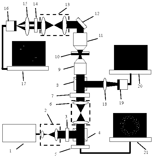
[0027] like figure 1 , the 532nm wavelength laser 1 passes through the beam expander and collimation system 2, becomes a parallel beam, and then passes through a linear polarizer 3 to become linearly polarized light. The expanded and collimated linearly polarized light enters the first beam splitter 4 and then vertically enters the reflective spatial light modulator 5 (model Holoeye Pluto, resolution 1080×1920). The third computer 21 loads the phase modulation map of the independently adjustable multi-focus spot to the reflective spatial light modulator 5 . After ...


PUM


Abstract

The invention discloses a device and method for detecting the polarization orientation of sub-wavelength scale multi-focus spots. After the angularly polarized laser beam is modulated by a phase-only spatial light modulator, multiple light spots with different polarization orientations can be generated on the focal plane. When the periodic slit microstructure on the surface of the gold film is placed on the focal plane, the incident light spot can be most effectively coupled into surface plasmons when the polarization direction of the light spot is perpendicular to the orientation of the slit. When the polarization direction of the light spot is parallel to the orientation of the slit, the incident light spot can hardly excite surface plasmons. When the polarization direction of the light spot and the orientation of the slit form an angle less than 90 degrees, the coupling efficiency is proportional to the square of the sine of the angle. The surface plasmon intensity at the position of multiple light spots can be observed through the leakage radiation microscopy imaging system, so as to realize the detection of the polarization orientation of each light spot.

Description

technical field [0001] The invention relates to a device for detecting the polarization orientation of multi-focus light spots on a sub-wavelength scale, and also relates to a method for detecting the polarization orientation of multi-focus light spots on a sub-wavelength scale. Background technique [0002] The laser beam is focused by a high numerical aperture objective lens to produce a spot of subwavelength size. Special phase modulation, amplitude modulation and polarization modulation of the incident laser can produce various special-shaped spots, such as needle spot, ring spot, spherical spot, longitudinally polarized spot, helical spot, two-dimensional array spot, three-dimensional array spot , chain facula, etc. These special spots can be applied in many fields such as optical data storage, laser particle manipulation, atomic waveguide, fluorescence super-resolution imaging, and laser micro-nano processing. [0003] The polarization direction of the light spot is ...

Claims


Application Information

Patent Timeline
Patent Type & Authority Patents(China)
IPC IPC(8): G01J4/00
CPCG01J4/00G01J4/04
Inventor 陈建农朱林伟李志刚徐钦峰
Owner LUDONG UNIVERSITY
Why Eureka
Try Eureka