An electromagnetic bearing switched reluctance motor system and control method

A switched reluctance motor, reluctance motor technology, applied in electrical components, holding devices with magnetic attraction or thrust, etc., can solve problems such as increased failure rate of power systems, limited application occasions, and poor corrosion resistance.

Active Publication Date: 2019-03-19
南京埃克锐特机电科技有限公司
View PDF4 Cites 0 Cited by
  • Summary
  • Abstract
  • Description
  • Claims
  • Application Information

AI Technical Summary

Problems solved by technology

Due to the use of permanent magnets to generate bias magnetic flux, permanent magnet bias magnetic bearings have a large levitation force / current ratio, high power density, low loss, and high efficiency, but permanent magnets are sensitive to temperature rise and have poor corrosion resistance. There is a risk of demagnetization or demagnetization in long-term operation, so its application is limited, and the storage of permanent magnets is limited, and the price is relatively expensive; and electromagnetic bearings can effectively solve the above problems of permanent magnets due to the use of electric excitation, but the control variable more, the number of power system branches also increases, the failure rate of the power system also increases, and the power density is lower; moreover, the switching reluctance motor and magnetic bearing in the traditional magnetic levitation switched reluctance motor system are independent of each other, the integration level is not high, the power system is huge, and the cost is high

Method used


Image

  • An electromagnetic bearing switched reluctance motor system and control method
  • An electromagnetic bearing switched reluctance motor system and control method
  • An electromagnetic bearing switched reluctance motor system and control method

Examples


Embodiment Construction

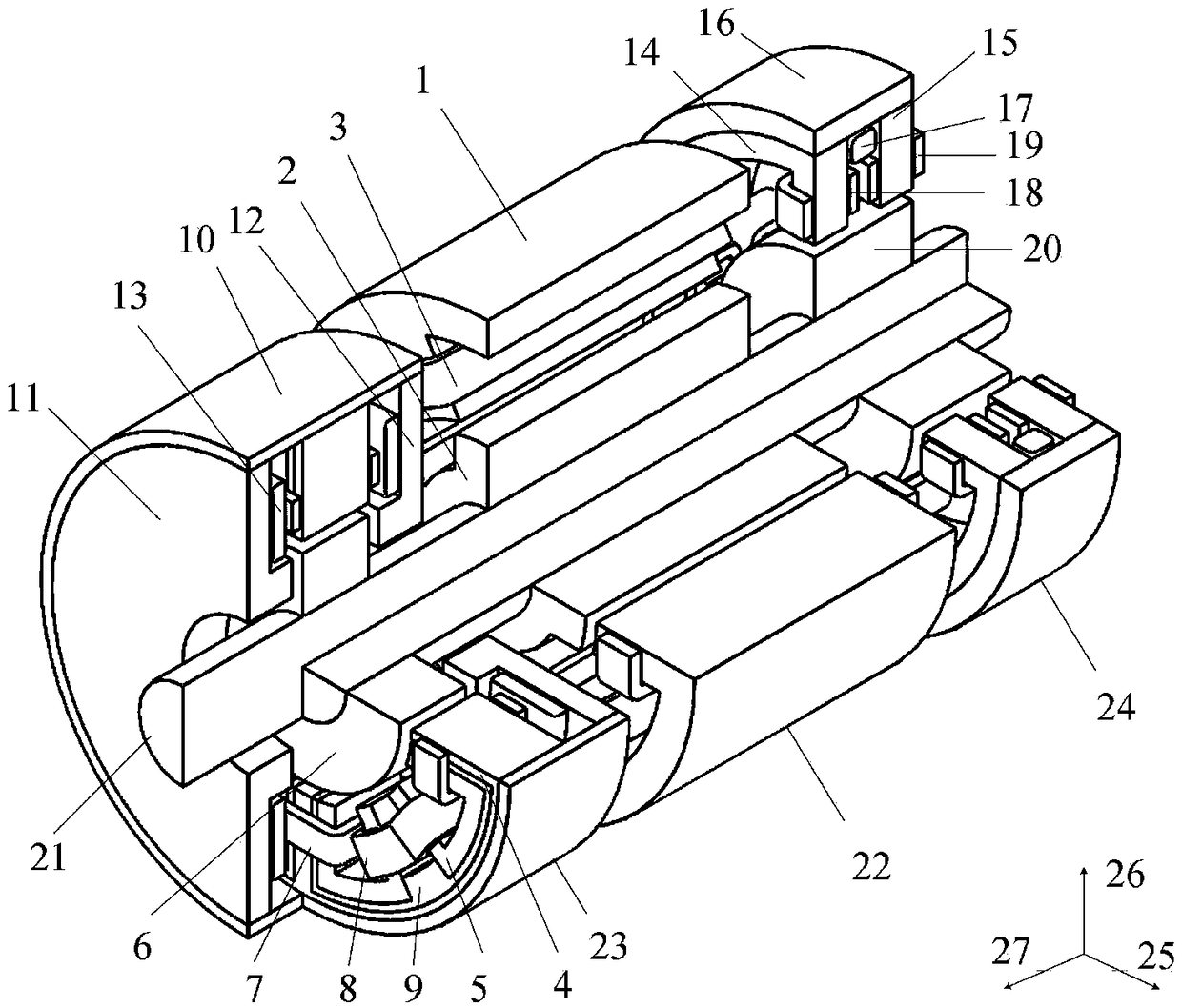
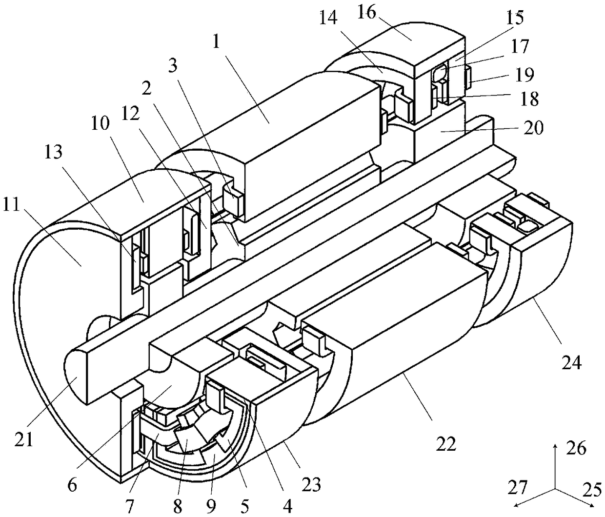
[0083] The technical scheme of an electromagnetic bearing switched reluctance motor system and control method of the present invention will be described in detail below in conjunction with the accompanying drawings:

[0084] Such as figure 1 Shown is a three-dimensional structural schematic diagram of embodiment 1 of the electromagnetic bearing switched reluctance motor system of the present invention, wherein, 1 is the stator of the reluctance motor, 2 is the rotor of the reluctance motor, 3 is the armature coil, 4 is the radial stator II, 5 is the radial stator Ⅰ, 6 is the magnetic bearing rotor Ⅰ, 7 is the bias coil Ⅰ, 8 is the radial levitation coil Ⅰ, 9 is the non-magnetic member, 10 is the annular magnetic yoke Ⅰ, 11 is the axial stator Ⅰ, 12 is the axial stator II, 13 is the axial suspension coil, 14 is the radial stator III, 15 is the radial stator IV, 16 is the annular magnetic yoke II, 17 is the bias coil II, and 18 is the radial suspension coil II , 19 is a radial ...


PUM


Abstract

The invention discloses an electromagnetic bearing switch magnetic resistance motor system and a control method. The motor system comprises a switch magnetic resistance motor, a three-DOF magnetic bearing and a radial magnetic bearing. Bias windings of the two magnetic bearings are connected in series and are then connected with DC buses of asymmetric half-bridge power converters of m phase armature windings of a switch magnetic resistance motor through four diodes, the m phase armature windings employ a traditional switch magnetic resistance driving mode, under the rectification effect of thefour diodes, a continuous invariant current is generated in a bias winding to provide bias magnetic flux for the two magnetic bearings; through reasonable control on currents of the five suspension windings, five-DOF suspension operation can be realized, mutual decoupling among five suspension forces is carried out, and decoupling between the suspension forces and torques is carried out. The motor system is advantaged in that the integration degree is high, the dynamo-electric energy conversion utilization rate is high, control variables are in a small quantity, suspension control is simple,reliability is high, the motor system has no permanent magnet, so working environment adaptability is strong, and the motor system is especially suitable for high-speed or super-speed application occasions.

Description

technical field [0001] The invention relates to an electromagnetic bearing switched reluctance motor system and a control method, belonging to the technical field of magnetic levitation switched reluctance motors and their control. Background technique [0002] The magnetic levitation switched reluctance motor system usually consists of a switched reluctance motor and two magnetic levitation bearings. It not only has the advantages of no friction and no lubrication of the magnetic levitation bearing, but also can give full play to the high speed and environmental adaptability of the switched reluctance motor. , has unique advantages in military and civilian applications such as aerospace, flywheel energy storage, high-speed centrifuges, high-speed blowers, and high-speed spindle motors. [0003] Magnetic suspension bearings can be divided into permanent magnet bias magnetic bearings and electromagnetic bearings according to different excitation methods. Due to the use of pe...

Claims


Application Information

Patent Timeline
Patent Type & Authority Patents(China)
IPC IPC(8): H02N15/00
Inventor 刘泽远蔡骏
Owner 南京埃克锐特机电科技有限公司
Why Eureka
Try Eureka