Low-water-loss rainwater filter tank

A filter tank and rainwater technology, which is applied in the direction of filter circuit, filter separation, water/sewage treatment, etc., can solve the problems of large load of sewage plants, high concentration of pollutants, and little consideration of initial rainwater filtration and purification treatment, etc., to achieve good treatment effect , good effect, simple setting effect

Inactive Publication Date: 2018-01-09
WUHAN SHENGYU DRAINING SYST
View PDF15 Cites 2 Cited by
  • Summary
  • Abstract
  • Description
  • Claims
  • Application Information

AI Technical Summary

Problems solved by technology

[0004] At present, the collection and treatment of initial rainwater in our country is still in its infancy. The collection of initial rainwater is only to prevent it from being discharged into the water body to pollute the water quality. However, little consideration is given to the filtration and purification treatment of initial rainwater, and most of it is directly discharged into the municipal domestic sewage pipe network.
The concentration of pollutants contained in the initial rainwater is relatively high, especially the initial rainwater on the road. Direct discharge into the domestic sewage pipe network will bring a greater load to the sewage plant

Method used


Image

  • Low-water-loss rainwater filter tank
  • Low-water-loss rainwater filter tank
  • Low-water-loss rainwater filter tank

Examples


Embodiment 1

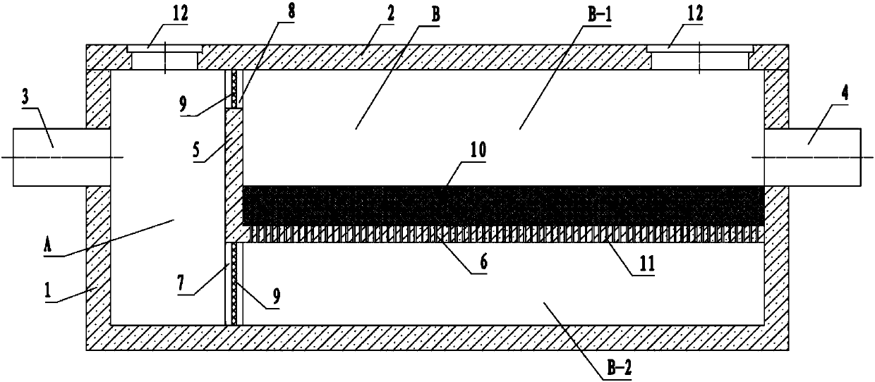
[0055] The structure of a low water loss rainwater filter pool in this embodiment is as follows: figure 1 As shown, the filter pool includes a well body 1, a cover plate 2 located above the well body, a water inlet pipe 3 and an outlet pipe 4 respectively located at the front and rear ends of the well body. The inside of the well body also includes a retaining wall 5 arranged longitudinally (that is, downward from the cover plate) to divide the well body into two parts, the pre-sedimentation area A and the treatment area B. The inside of the well body further includes a support plate 6 arranged laterally between the retaining wall 5 and the rear end well body to divide the treatment area B into the upper part as the filtering area B-1 and the lower part as the settlement area B-2.

[0056] Wherein, the lower end of the retaining wall 5 is provided with a water tank 7 from the bottom surface of the well body, and the upper end is provided with an overflow tank 8 from the cover ...

Embodiment 2

[0061] A kind of method that utilizes the low water loss rainwater filter pond in embodiment 1 to handle rainwater is:

[0062] When it rains, runoff rainwater from streets, highways, parking lots, residential areas or shopping malls, and the ground, which carry pollutants such as particulate matter, suspended matter, floating matter, nitrogen, and phosphorus, enters the pre-settling area A of the well body through the water inlet pipe 3, which is greater than Pollutants such as particulates, suspended solids and floating solids in the aperture of the slag blocking net 9 on the water tank 7 will be intercepted in the pre-sedimentation zone A, and most of the particulates entering the settlement zone B-2 will also settle in the sedimentation zone under the action of gravity. Area. With the rise of the water level in the settlement area, when it reaches the position of the support plate 6, the rainwater will flow through the filter medium 10 from the water hole 11, and after bei...

Embodiment 3

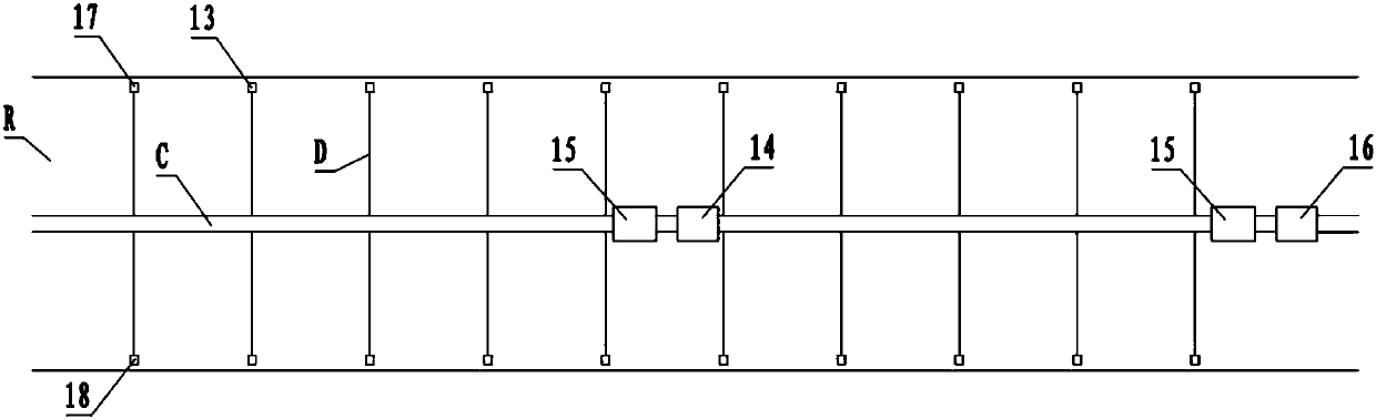
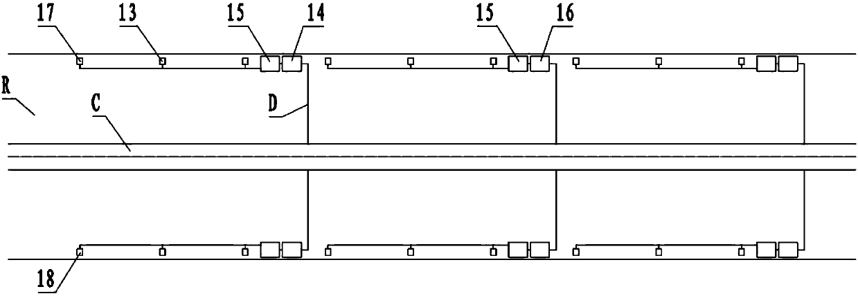
[0066] The structure of a road segment rainwater treatment system in this embodiment is as follows: figure 2 As shown, the system includes a main rainwater pipe C on a municipal road R, a branch rainwater pipe D connected to the main rainwater pipe C, and a rainwater outlet 13 at the end of the branch rainwater pipe D. The rainwater main pipe C is segmented according to the length of 500-800m, and the low water loss rainwater filter pool 14 described in the embodiment 1 is set on each section of the rainwater main pipe C. The water inlet pipe 3 and the water outlet pipe 4 at the front and rear ends of the well body of the filter pool 14 communicate with the front and back (ie upstream and downstream) of the rainwater main pipe C respectively.

[0067] Further, a hydrocyclone separator 15 is also arranged in front of the low water loss rainwater filter tank 14 (ie, the water inlet direction of the filter tank).

[0068] Further, a cylindrical filter system 16 is also provided...


PUM


Abstract

The invention relates to a low-water-loss rainwater filter tank. The low-water-loss rainwater filter tank comprises a well body, a cover plate arranged above the well body, a water inlet pipe and a water outlet pipe which are arranged at the front end and the rear end of the well body, a retaining wall longitudinally arranged inside the well body and a supporting plate arranged between the retaining wall and the rear end of the well body, wherein the retaining wall and the supporting plate divide the interior of the well body into a presedimentation zone at the left side, the upper part of theright side is a filtering zone and the lower part of the right side is a sedimentation zone; the presedimentation zone is communicated with the water inlet pipe; the filtering zone is communicated with the water outlet pipe; the retaining wall is provided with a water flowing channel from the bottom surface of the well body, and the upper end of the retaining wall is provided with an overflow channel from the cover plate; a filtering medium is paved above the supporting plate; and a water flowing hole is formed in the supporting plate. The low-water-loss rainwater filter tank provided by theinvention has a good rainwater treatment effect, and pollution of pollutants on natural water body can be effectively reduced. External power drive is not required in a treatment process, and normal flood discharge is not influenced. Besides, water loss in the treatment process is low.

Description

technical field [0001] The invention relates to a rainwater purification device, in particular to a low water loss rainwater filter pool. Background technique [0002] With the acceleration of urbanization, the impermeable area on the ground has increased significantly, and pollutants have gradually accumulated on these impermeable ground. When it rains, the rainwater washes the ground and the pollutants are washed into the rainwater runoff system to form rainwater runoff pollution. Rainwater runoff pollution is a kind of diffuse pollution. Pollutants enter natural water bodies and cause water pollution. The pollutants exist in the form of particulate matter, suspended matter, and floating matter, and contain toxic and harmful substances such as organic matter and heavy metals. Therefore, the process of urbanization and industrialization has led to increasingly serious water crisis and rain and flood hazards. [0003] With the aggravation of water source crisis and rain and...

Claims


Application Information

Patent Timeline
Patent Type & Authority Applications(China)
IPC IPC(8): B01D36/04E03F5/14E03F3/02
Inventor 汤杰
Owner WUHAN SHENGYU DRAINING SYST
Why Eureka
Try Eureka