A gas hydrate decomposition and reaction liquid recovery device

A gas hydrate and recovery device technology, which is applied in the direction of gas fuel, separation method, and dispersed particle separation, etc., can solve the problems of insufficient use of gas waste heat, energy waste, etc., achieve smooth flow of gas phase, improve decomposition efficiency, and reduce gas loss Effect

Active Publication Date: 2020-03-24
GUANGZHOU INST OF ENERGY CONVERSION - CHINESE ACAD OF SCI
View PDF10 Cites 0 Cited by
  • Summary
  • Abstract
  • Description
  • Claims
  • Application Information

AI Technical Summary

Problems solved by technology

In addition, for the hydrate method combined with the chemical absorption method, during the regeneration process of the absorption liquid, a lot of gas waste heat is not fully utilized, resulting in a lot of energy waste

Method used


Image

  • A gas hydrate decomposition and reaction liquid recovery device
  • A gas hydrate decomposition and reaction liquid recovery device

Examples


Embodiment

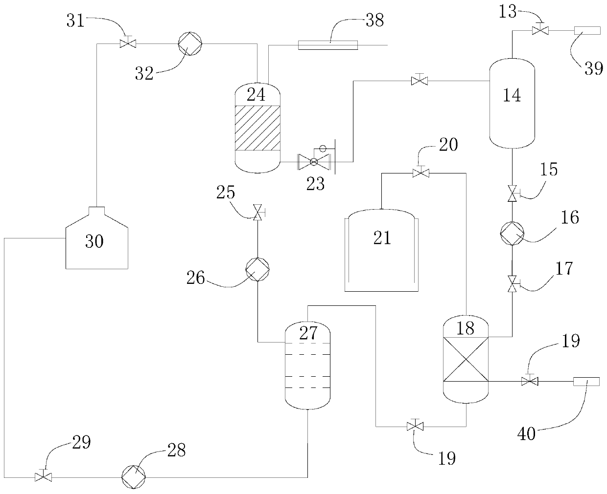
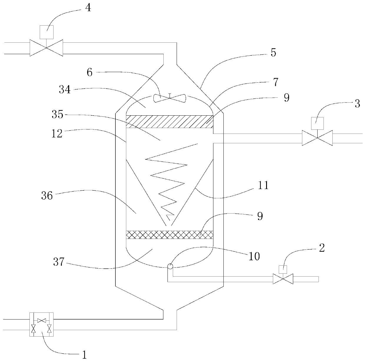
[0025] refer to figure 1 and figure 2, is a gas hydrate decomposition and reaction liquid recovery device, including a three-phase separator 14, a gas hydrate decomposition unit 18, a carbon dioxide collection tank 21, an absorption liquid regeneration unit 27, a chemical absorption tower 24, and an absorption tank containing ethanolamine solution Liquid storage tank 30, slurry pump 16, back pressure valve 23, first corrosion-resistant pump 26, second corrosion-resistant pump 28, third corrosion-resistant pump 32; in this embodiment, the structures are connected by pipelines, and the pipelines Add some stop valves and one-way air valves according to actual needs. The IGCC synthesis gas and its slurry separated by the hydrate method are sequentially input from the hydrate slurry inlet 39 and the input end of the first stop valve 13, and the output end of the first stop valve 13 is connected to the input end of the three-phase separator 14; The first output end of the three-p...


PUM

PropertyMeasurementUnit
heightaaaaaaaaaa
diameteraaaaaaaaaa
heightaaaaaaaaaa

Abstract

The invention discloses a gas hydrate dissociation and reaction liquid recovery device. The device comprises a three-phase separator, a gas hydrate dissociation unit, a carbon dioxide collection tank,an absorption liquid regeneration unit, a chemical absorption tower, an absorption liquid storage tank stored with an ethanol amine solution, a slurry pump, a counterbalance valve, a first anticorrosive pump, a second anticorrosive pump and a third anticorrosive pump. The device can be used for solving the problem of heat supply of hydrate dissociation; hydrate slurry entering a swirl chamber canbe kept in the chamber for a longer period, the slurry descends in the swirling process, gas rises, vacuum is formed in the swirling center in the swirling process, and hydrate dissociation is favored; an exhaust fan is beneficial to quick emission of dissociated gas, gas consumption can be reduced, and hydrate secondary generation which may possibly occur can be reduced; and as filter pores areformed in the conical bottom of the swirl chamber and the outer wall of the inner chamber of the lower chamber body, high-temperature regenerated gas enters inside the swirl chamber to perform heat convection with hydrate slurry, and the hydrate dissociation efficiency can be greatly improved.

Description

technical field [0001] The invention relates to the field of hydrate formation and decomposition, in particular to a gas hydrate decomposition and reaction liquid recovery device suitable for a hydrate method combined with a chemical absorption method. Background technique [0002] The fuel gas (40%mol CO2 / 60%molH2) produced by the integrated gasification combined cycle power generation system (IGCC) is the main target of global carbon dioxide emission reduction. A recent detailed study by the US Department of Energy (DOE) and EPRI clearly shows that the system's CO2 capture process increases the cost per net kilowatt of power by 32%. Therefore, an effective carbon dioxide capture process that can greatly reduce energy consumption is of great significance for the promotion and further development of IGCC systems. Currently, carbon dioxide capture processes mainly include chemical absorption, adsorption, and membrane separation. However, these processes have their own appli...

Claims


Application Information

Patent Timeline
Patent Type & Authority Patents(China)
IPC IPC(8): C10L3/10B01D53/14
Inventor 李小森余益松徐纯刚陈朝阳黄宁生李刚
Owner GUANGZHOU INST OF ENERGY CONVERSION - CHINESE ACAD OF SCI
Why Eureka
Try Eureka