Accident quick gate falling speed regulation device for wind hoist and control method
A technology of speed regulating device and hoist, which is applied in sea area engineering, construction, barrage/weir, etc., and can solve the problems of centrifugal flying pendulum governor's balance speed increase, increase, and affect safe operation, etc.
- Summary
- Abstract
- Description
- Claims
- Application Information
AI Technical Summary
Problems solved by technology
Method used
Image
Examples
Embodiment 1
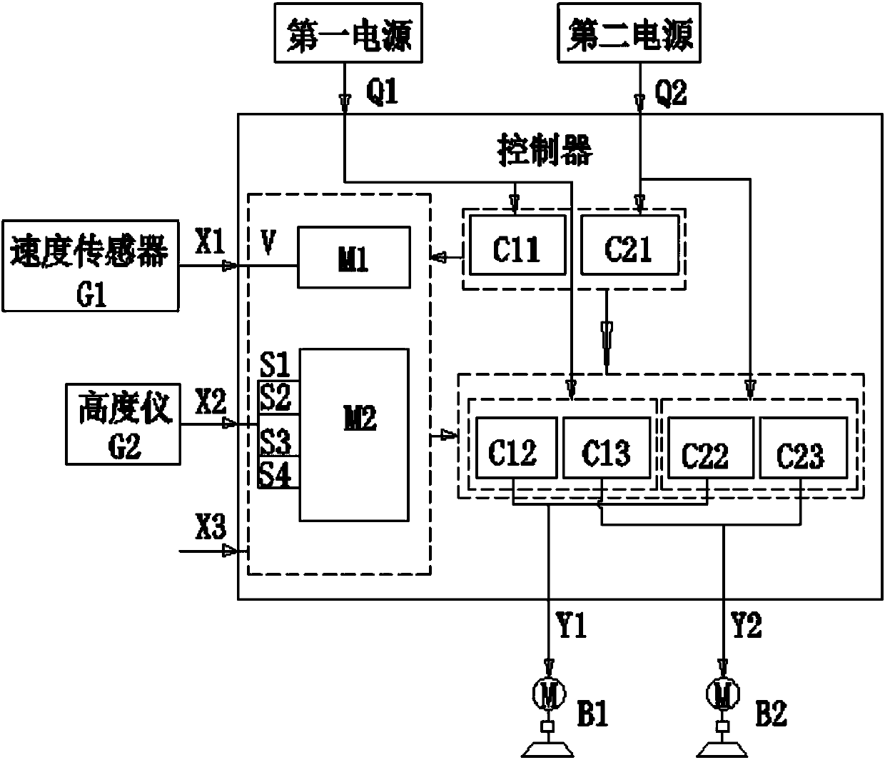
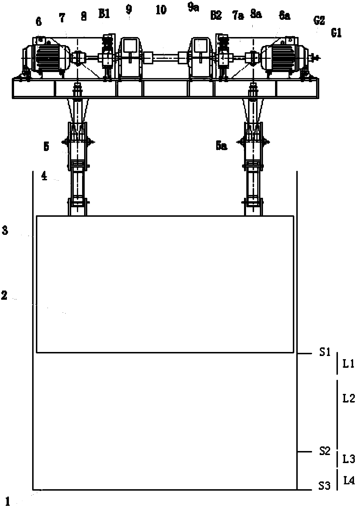
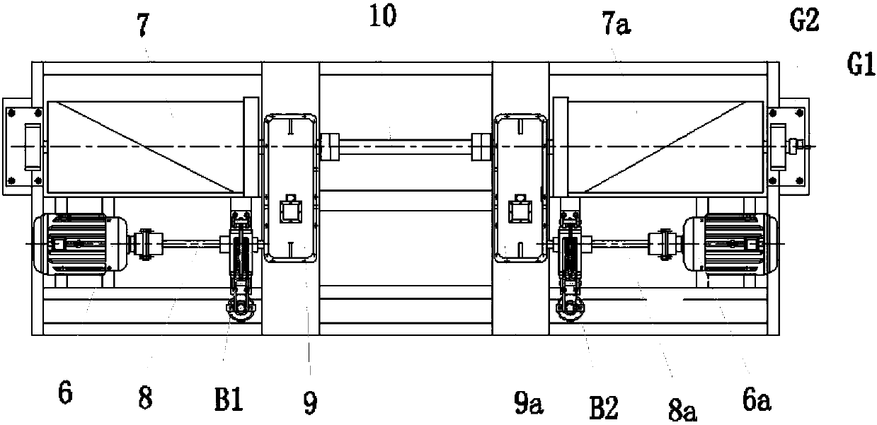
[0036] Example 1, see figure 1 , figure 2 , image 3
[0037] The speed regulating device of the present invention includes a brake B1 and another brake B2, a speed sensor G1, an altimeter G2 and a controller. The controller includes a first power input terminal Q1, a second power input terminal Q2, a first power supply circuit C11 and a second power supply circuit C21, a first conversion circuit C12, a second conversion circuit C13, a third conversion circuit C22 and a fourth conversion circuit Circuit C23, speed comparison processor M1 and position detection processor M2, the first power input terminal Q1 is connected to the input terminal of the first power supply circuit C11, the second power input terminal Q2 is connected to the input terminal of the second power supply circuit C21, and the second power supply input terminal Q2 is connected to the input terminal of the second power supply circuit C21. A power supply input terminal Q1 is also connected with the input t...
Embodiment 2
[0048] Example 2, see Figure 6
[0049] Embodiment 2 is a form in which the brake B and another brake B2 are arranged on both ends of the high-speed shaft of the reducer 9, and the first drum 7 and the second drum 7a are also arranged on the low-speed shaft of the reducer 9 at the same time. Both ends of the shaft are extended. There is only one speed reducer 9 among the embodiment 2.
Embodiment 3
[0050] Example 3, see Figure 7
[0051] Embodiment 3 is a form in which the brake B is arranged on the connecting end of the motor 6 and the floating shaft 8, and another brake B2 is arranged on the connecting end of the reducer 9 and the floating shaft 8, while the first rotating drum 7 and the second rotating drum 7a is also arranged on both ends of the low-speed shaft of the reducer 9 at the same time. In embodiment 3, there is only one speed reducer 9, one motor 6 and one floating shaft 8.
PUM
 Abstract
Description
Claims
Application Information
 - R&D
- Intellectual Property
- Life Sciences
- Materials
- Tech Scout
- Unparalleled Data Quality
- Higher Quality Content
- 60% Fewer Hallucinations
Browse by: Latest US Patents, China's latest patents, Technical Efficacy Thesaurus, Application Domain, Technology Topic, Popular Technical Reports.
© 2025 PatSnap. All rights reserved.Legal|Privacy policy|Modern Slavery Act Transparency Statement|Sitemap|About US| Contact US: help@patsnap.com


