All working condition standard emission control method for thermal power unit denitration system

A technology for thermal power unit and emission control, applied in adaptive control, general control system, control/regulation system, etc., can solve the problems of denitration system operation performance impact, poor automatic input rate and input effect, and large control lag, etc. Achieve the effect of improving closed-loop stability and anti-disturbance ability, improving automation level, and accurately controlling the amount of ammonia injection

Active Publication Date: 2018-01-09
NORTH CHINA ELECTRIC POWER UNIV (BAODING)
View PDF10 Cites 31 Cited by
  • Summary
  • Abstract
  • Description
  • Claims
  • Application Information

AI Technical Summary

Problems solved by technology

[0004] In engineering practice, thermal power plants mostly rely on manual adjustment of valve opening or traditional PID controllers to control the amount of ammonia injection. The control effect is not ideal. The NOx concentration at the SCR outlet of some power plants exceeds the national emission limit for air pollutants. value, and cannot ensure that the NOx concentration at the SCR outlet is stable at the set value while realizing the optimal control of the amount of ammonia injection
Due to problems such as imperfect control strategy design, unclear control objectives, and poor on-site measurement conditions, the SCR denitrification control of some thermal power units has a large lag. When the SCR inlet NO X When the concentration measuring point is purged, the value of the measuring point is in a distorted state. At this time, the amount of ammonia injection cannot be timely aimed at the NO at the SCR inlet. X Changes in concentration are adjusted accordingly, resulting in poor automatic input rate and input effect of the system, which significantly affects the operating performance of the entire denitrification system

Method used


Image

  • All working condition standard emission control method for thermal power unit denitration system
  • All working condition standard emission control method for thermal power unit denitration system
  • All working condition standard emission control method for thermal power unit denitration system

Examples


Embodiment Construction

[0028] The present invention will be described in further detail below in conjunction with the accompanying drawings.

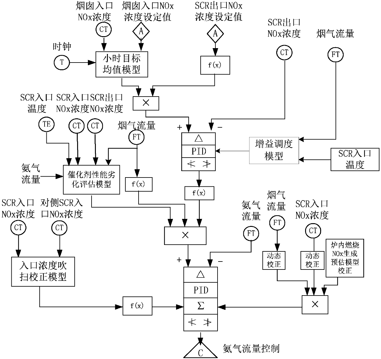
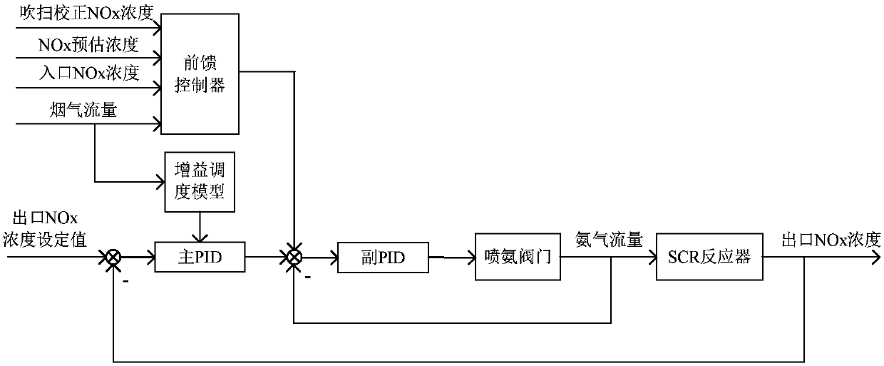
[0029] figure 1 It is the overall scheme diagram of the SCR denitrification automatic control system of the present invention. In the figure, there is mainly an hourly target average model. According to the measured value and set value of the NOx concentration at the chimney inlet and the time measured by the clock as the basis, the weighted average of the NOx concentration deviation at the chimney inlet per hour is obtained, combined with the NOx concentration at the outlet of the denitrification reactor. The set point can be more accurate and representatively reflect the NOx concentration level at the chimney inlet. Catalyst performance degradation evaluation model, the catalyst activity b is obtained according to the measured values ​​of the inlet and outlet NOx concentrations, flue gas flow and ammonia flow of the denitrification reactor, so as to reflec...


PUM


Abstract

The invention provides an all working condition standard emission control method for a thermal power unit denitration system. The method comprises the steps that a main ring PID controller, a sub-ringPID controller and a feedforward controller are arranged in a denitration control system; the main ring PID controller calculates an ammonia injection control signal according to an outlet NOx concentration set value and an outlet NOx concentration feedback signal; the feedforward controller calculates an ammonia injection feedforward control signal according to the purge correction NOx concentration, the NOx estimated concentration, the inlet NOx concentration and the flue gas flow; and the sub-ring PID controller controls the opening of an ammonia injection valve according to the ammonia injection control signal, the ammonia injection feedforward control signal and an ammonia flow feedback signal. According to the invention, a gain scheduling model and an hour mean model are added intoa main ring to realize automatic control of the variable working condition of the denitration system; an inlet concentration purge correction model is introduced into a sub-ring to realize dynamic ammonia injection correction; the ammonia injection is accurately controlled; and a technical support is provided for whole process robustness and all working condition standard emission.

Description

technical field [0001] The invention relates to a control method that can effectively improve the robustness of the whole process of the denitrification system of a thermal power generating set and realize discharge up to the standard in all working conditions, and belongs to the technical field of power generation. Background technique [0002] At present, environmental pollution has become an important factor that plagues social development and human life and health. With the rapid development of the electric power industry, the parameters and capacity of coal-fired power generation units continue to increase, and the pollution caused by NOx emitted by coal-fired power plants to the atmosphere It is becoming more and more serious, photochemical smog has appeared in many areas, and its pollution is still increasing. Controlling the emission of nitrogen oxides has become a key pollution control task, and realizing ultra-low and near-zero emissions of nitrogen oxides is an im...

Claims


Application Information

Patent Timeline
Patent Type & Authority Applications(China)
IPC IPC(8): G05B13/04
Inventor 危日光梁胜莹高建强武旭阳赵晶
Owner NORTH CHINA ELECTRIC POWER UNIV (BAODING)
Why Eureka
Try Eureka