Suppressor for high-frequency output of gyrotron traveling-wave tube
A high-frequency output and suppressor technology, which is applied in the microwave field, can solve the problems of impure output mode and achieve the effect of ensuring high-efficiency transmission, reducing content, and ensuring high-performance and stable operation
- Summary
- Abstract
- Description
- Claims
- Application Information
AI Technical Summary
Problems solved by technology
Method used
Image

Examples
Embodiment Construction
[0020] The specific embodiments of the present invention are described below so that those skilled in the art can understand the present invention, but it should be clear that the present invention is not limited to the scope of the specific embodiments. For those of ordinary skill in the art, as long as various changes Within the spirit and scope of the present invention defined and determined by the appended claims, these changes are obvious, and all inventions and creations using the concept of the present invention are included in the protection list.
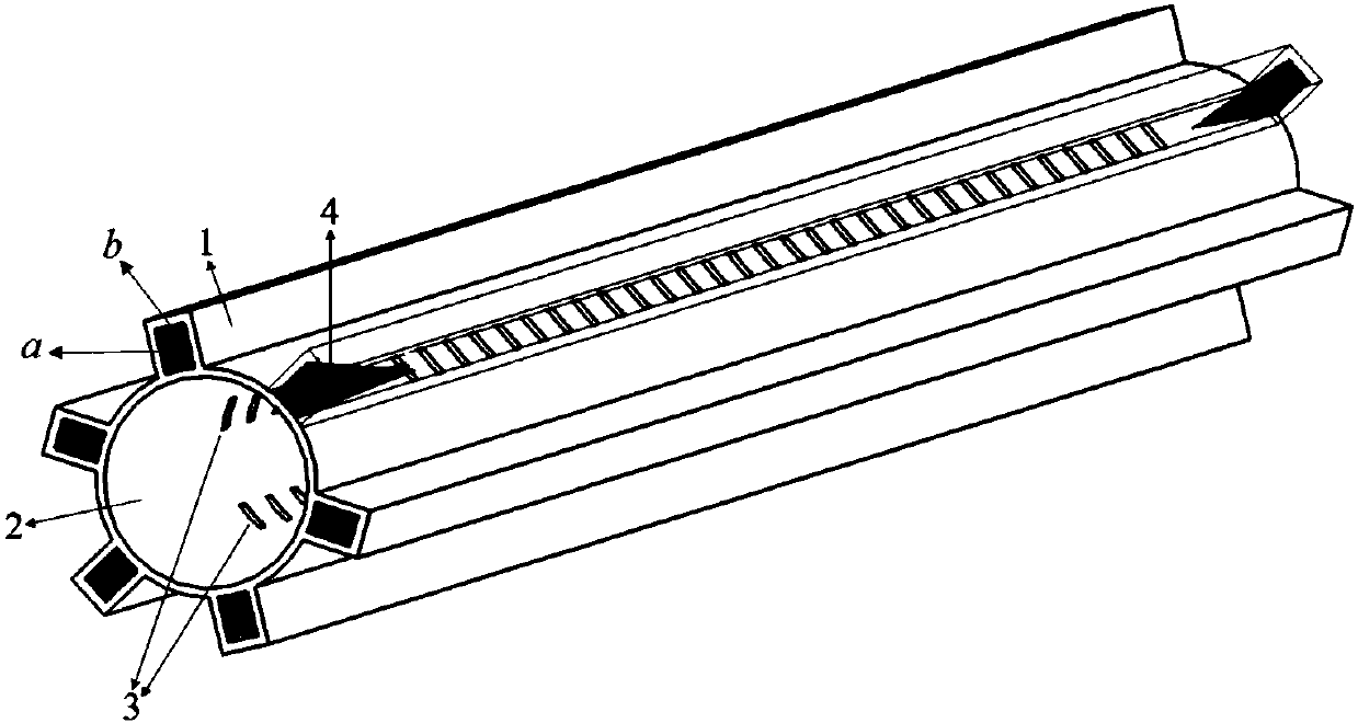
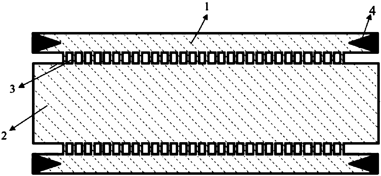
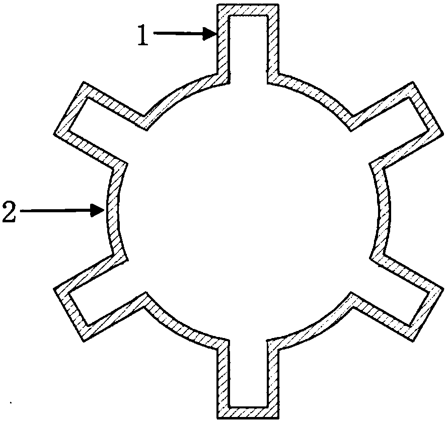
[0021] refer to Figure 1 to Figure 3 as shown, figure 1 A schematic diagram showing the structure of the suppressor for the high-frequency output of the gyrotraveling wave tube with 6 sub-waveguides 1 and 30 rectangular coupling holes; figure 2 A cross-sectional view showing the suppressor for the high-frequency output of the gyrotron TWT; image 3 A schematic cross-sectional view of the suppressor along the coupling ho...
PUM
| Property | Measurement | Unit |
|---|---|---|
| Thickness | aaaaa | aaaaa |
Abstract
Description
Claims
Application Information
 - Generate Ideas
- Intellectual Property
- Life Sciences
- Materials
- Tech Scout
- Unparalleled Data Quality
- Higher Quality Content
- 60% Fewer Hallucinations
Browse by: Latest US Patents, China's latest patents, Technical Efficacy Thesaurus, Application Domain, Technology Topic, Popular Technical Reports.
© 2025 PatSnap. All rights reserved.Legal|Privacy policy|Modern Slavery Act Transparency Statement|Sitemap|About US| Contact US: help@patsnap.com