Table model numerical control cutting machine

A cutting machine, desktop technology, applied in manufacturing tools, plasma welding equipment, welding equipment and other directions, can solve the problems of unsatisfactory dust removal effect, complex cleaning structure, difficult to clean waste, etc. Cleverly designed effects

Pending Publication Date: 2018-01-19
JIANGSU ZHENGHE HEAVY IND CO LTD
View PDF9 Cites 9 Cited by
  • Summary
  • Abstract
  • Description
  • Claims
  • Application Information

AI Technical Summary

Problems solved by technology

But the existing dust removal device is relatively simple, can only remove dust as a whole, and the dust removal effect is not ideal; moreover, the collected waste after cutting the workpiece is not easy to clean up, the existing cleaning structure is more complicated, and the operation is inconvenient

Method used


Image

  • Table model numerical control cutting machine
  • Table model numerical control cutting machine
  • Table model numerical control cutting machine

Examples


Embodiment 1

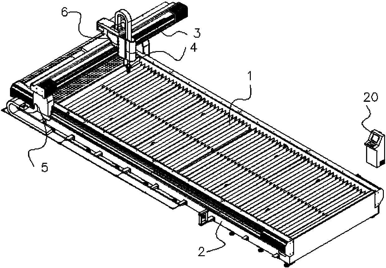
[0048] Embodiment 1: a kind of desktop numerical control cutting machine, such as Figure 1-1 to Figure 10 As shown, the length direction of the cutting machine is defined as longitudinal, including workbench 1, frame 2, beam 3 and cutting torch 4, the frame is located on both sides of the longitudinal direction of the workbench, and the beam is located on the Above the workbench, the cutting torch is connected to the crossbeam, including a longitudinal transmission device 5 for driving the crossbeam to move longitudinally, a transverse transmission device 6 for driving the cutting torch to move laterally, and a horizontal transmission device for driving the cutting torch to move horizontally. The lifting device 7 that moves up and down and the ventilation and dust removal device for ventilation and dust removal;

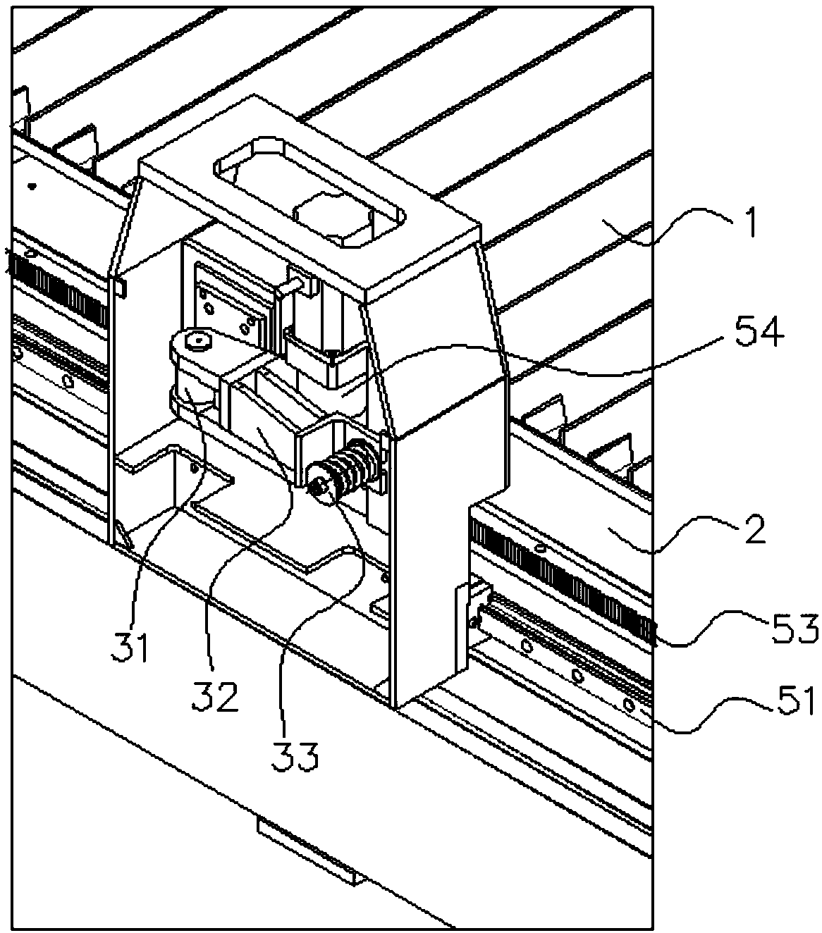
[0049] The longitudinal transmission device 5 includes a first track 51, a first gear 52, a first rack 53 and a first motor 54, the first track and the first rack a...

Embodiment 2

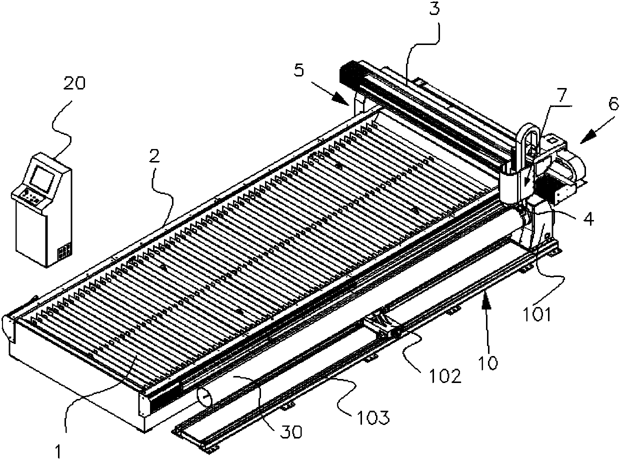
[0069] Embodiment 2: a kind of desktop numerical control cutting machine, such as Figure 1-2 Shown, similar to embodiment 1 structure, difference is:

[0070] The cutting machine also includes a pipe cutting unit 10, the pipe cutting unit is located on the side of the workbench and parallel to the workbench, the pipe cutting unit includes a pipe positioning seat 101, a pipe moving frame 102 and a third guide rail 103, the pipe positioning seat is fixed on one end of the third guide rail, the pipe moving frame is located on the third guide rail and can move along the third guide rail, the pipe 30 is located on the pipe moving frame and the pipe One end is limited by the pipe positioning seat.

[0071] Working principle and working process of the present invention are as follows:

[0072] Place the workpiece to be cut on the workbench, start the cutting machine, under the control of the control system, the first motor of the longitudinal transmission device drives the beam th...


PUM

PropertyMeasurementUnit
thicknessaaaaaaaaaa

Abstract

The invention discloses a table model numerical control cutting machine. The table model numerical control cutting machine comprises a workbench, racks, a beam and a cutting torch. The racks are located on the two sides of the workbench. The beam is located above the workbench. The cutting torch is connected with the beam. The table model numerical control cutting machine further comprises a longitudinal transmission device for driving the beam to move longitudinally, a transverse transmission device for driving the cutting torch to move transversely, a lifting device for driving the cutting torch to move up and down and an air draft dedusting device for air draft dedusting. The air draft dedusting device is located below the workbench. The air draft dedusting device comprises hoppers, flow stabilization bins and air flues. Each hopper is provided with the corresponding flow stabilization bin located below the hopper and communicates with the flow stabilization bin through an air outlet of the hopper. Each flow stabilization bin communicates with the corresponding air flue through an air outlet of the flow stabilization bin. The table model numerical control cutting machine has thebeneficial effects that the structure is compact, the operation is easy, maintenance is convenient, the energy loss is low, and the dedusting efficiency is high; and the high speed and efficiency, stable quality and the like are achieved, and the table model numerical control cutting machine is suitable for cutting of plates or pipes.

Description

technical field [0001] The invention belongs to the technical field of automation equipment, and in particular relates to a cutting machine suitable for cutting tube and plate materials. Background technique [0002] The development of CNC cutting machines must adapt to the requirements of the development of modern machining industry. Cutting machine is divided into flame cutting machine, plasma cutting machine, laser cutting machine, water cutting and so on. Among them, the cutting speed of the plasma cutting machine is also very fast, and the cutting surface has a certain slope. The flame cutting machine is aimed at thicker carbon steel materials. [0003] Cutting metal sheets and other parts will produce smoke, debris and welding slag, which will pollute the related parts and workpieces on the machine tool, affecting normal cutting, and the smoke and dust will float out, which will have an impact on the operating environment, especially for operators of good health. T...

Claims


Application Information

Patent Timeline
Patent Type & Authority Applications(China)
IPC IPC(8): B23K10/00B23K7/00B23K7/10
Inventor 卢锋
Owner JIANGSU ZHENGHE HEAVY IND CO LTD
Why Eureka
Try Eureka