Self-cooled thermodynamic cycle method
A thermodynamic cycle and self-cooling technology, applied in heat pumps, refrigerators, refrigeration components, etc., can solve the problems of implementation methods and application field limitations, and achieve the effects of low cost, improved practicability, and high heat and mass transfer efficiency
- Summary
- Abstract
- Description
- Claims
- Application Information
AI Technical Summary
Problems solved by technology
Method used
Image

Examples
Embodiment approach 1
[0016] Embodiment 1, a self-cooling thermodynamic cycle using an independent heat pump:
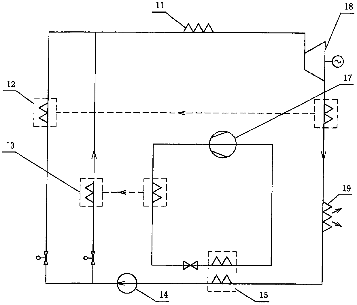
[0017] Such as figure 1 Shown is a self-cooling thermodynamic cycle that uses an independent heat pump process. After cooling or liquefaction by the heat pump heat absorbing heat exchanger 15 (for simplicity, the dotted line represents the heat exchange process, which has nothing to do with the heat exchanger structure, the same below), the heat The low-temperature working medium of the system completes the pressure boosting process through the pump 14, and after the pressure boosting, it passes through the heat pump process heat exchanger 13 and the heat recovery heat exchanger 12 to complete the preheating process, and completes the process of absorbing heat from the heat source through the heat source heater 11 to make the working medium become The power gas source, the power gas source enters the expansion work device 18, and the low-temperature gas working medium that completes the e...
Embodiment approach 2
[0022] Embodiment 2, regenerative heat pump
[0023] as attached Figure 4 A self-cooling thermodynamic cycle using a regenerative heat pump is shown in the attached figure 1 On the basis of the heat pump process, the heat recovery process is added before and after the booster device. The heat recovery process uses a heat recovery heat exchanger 16, and the heat exhaust heat exchanger and the heat recovery heat exchanger arranged on the outlet pipeline of the booster device are arranged in parallel to exchange heat synchronously. , can also be alternately arranged multiple times on the same pipeline for heat exchange.
[0024] as attached Figure 5 Shown is a self-cooling thermodynamic cycle using a heat recovery heat pump. The heat pump process uses a jet cyclone heat pump, and the heat pump booster 17 provides injection power for the jet cyclone 21 to realize the cooling of the system working fluid. Refrigeration and liquefaction become jet refrigeration and liquefaction ...
Embodiment approach 3
[0025] Embodiment 3, open self-cooling thermodynamic cycle
[0026] as attached Figure 7 In the open self-cooling thermodynamic cycle shown, a multi-stage compressor 31 is used in the boosting process, a compressor 35 is used in the heat pump process, and an expander 34 is added to recover the expansion work after heat exchange in the heat pump process. The low-temperature gas that comes out is sent to the cooling device 32 of the multi-stage compressor in the step-up process (for simplicity, only the dotted line represents the heat transfer process) to provide a cold source for it. Obviously, when the temperature of the heat pump gas coming out of the cooling device 32 is close to the ambient temperature, it is equivalent to transferring the exhaust heat of the multi-stage compressors in the boosting process to the preheating process through the heat pump, which is an open heat pump cycle. The working medium of the open thermal cycle is directly air or flue gas (for example...
PUM
 Abstract
Description
Claims
Application Information
 - R&D
- Intellectual Property
- Life Sciences
- Materials
- Tech Scout
- Unparalleled Data Quality
- Higher Quality Content
- 60% Fewer Hallucinations
Browse by: Latest US Patents, China's latest patents, Technical Efficacy Thesaurus, Application Domain, Technology Topic, Popular Technical Reports.
© 2025 PatSnap. All rights reserved.Legal|Privacy policy|Modern Slavery Act Transparency Statement|Sitemap|About US| Contact US: help@patsnap.com