
Eureka
For R&D, Eureka makes reading and utilizing patents & technical documents easy.
Eureka AIR
Designed for self-driven R&D workflows. Generate viable solutions, solve complex R&D challenges, empower your innovation with AI.

Eureka Materials
Designed for material experts only. Revolutionize your material R&D, from search, analyze, to developing new materials.

TechResearch
Generate reliable direction feasibility study reports for your R&D in just a few steps.

TechSeek
Discover and master advanced knowledge NOW. Basics, ideas, possibilities, all at once.

TechMind
As an expert in R&D Theories, TechMind can generates customized viable solutions instantly.

TechRisk
Analyze your overall solution with one click, know your potential R&D risks in advance.

TechMonitor
Get weekly tech updates, stay abreast of the latest tech innovations and key insights.
Heat supply device outputting hot oil
A heat supply device and heating device technology, applied in heat storage heaters, fluid heaters, lighting and heating equipment, etc., can solve the problems of increased installation workload, low heat exchange intensity, large thermal stress, etc., to reduce installation The effect of workload, enhanced furnace heat transfer, and enhanced heat transfer intensity
- Summary
- Abstract
- Description
- Claims
- Application Information
AI Technical Summary
Problems solved by technology
Method used
Image

Examples
Embodiment 1
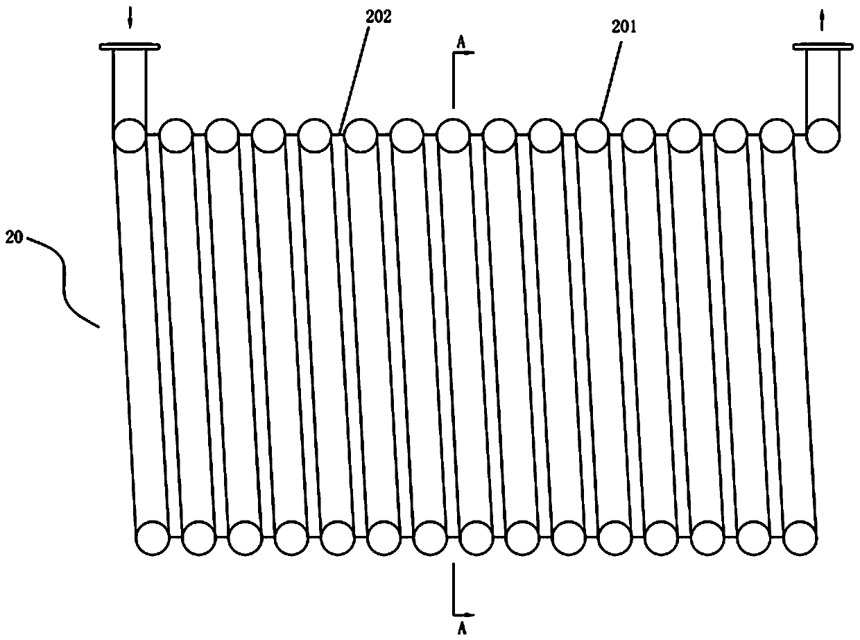
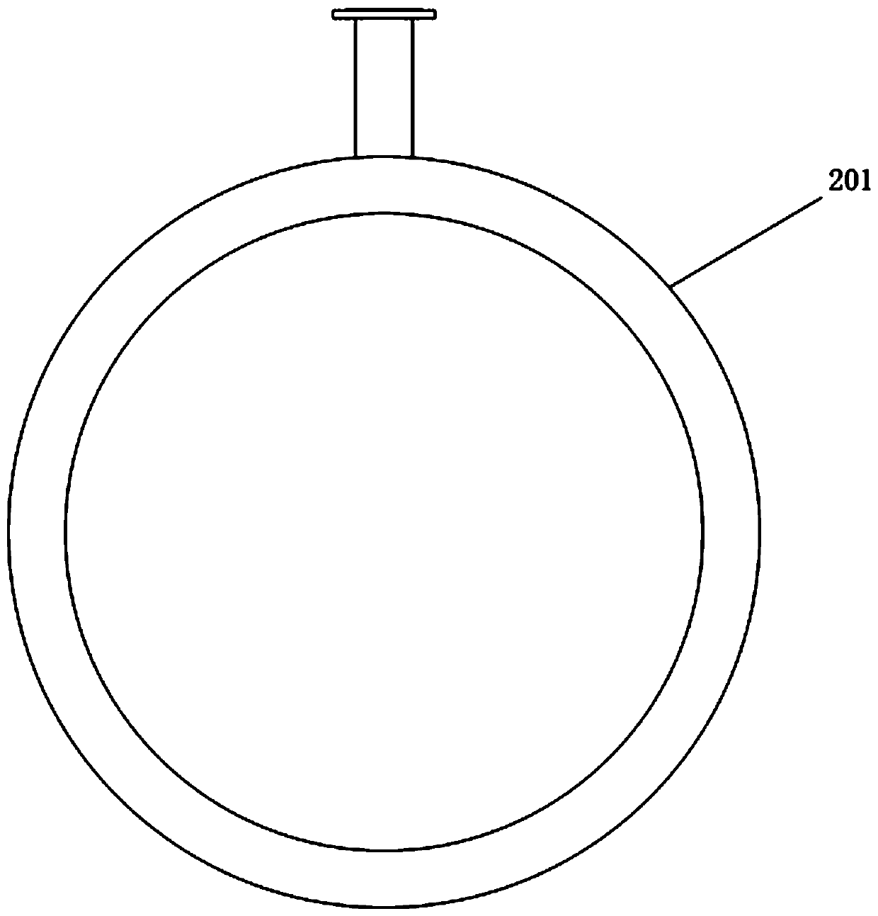
[0031] Such as figure 1 A kind of spiral coil membrane type fireplace hearth shown, it comprises: a spiral coil 201, a spiral sealing plate 202, the gap between each spiral of this spiral coil 201 is welded up with this spiral sealing plate 202, book To form a complete cylindrical membrane hearth 20 .
Embodiment 2
[0033] A spiral coil membrane fireplace body, which is provided with the spiral coil membrane fireplace chamber 20 in Embodiment 1, and end plates (not shown in the figure) are welded at both ends of the spiral coil membrane fireplace chamber 20, By means of this, a complete spiral coil membrane fireplace body 2 is formed.
[0034] The furnace body of embodiment 2 is convenient to use, and the simplest application is such as inputting heat into the furnace 20 of the spiral coil membrane fireplace body 2 through the end plate, such as inputting high-temperature flue gas, and cooling water from one end of the spiral coil tube 201 The cold water is input into the mouth, and the high-temperature flue gas scours the inner wall of the corrugated furnace horizontally, and the cold water is heated into hot water or steam, which is output from the hot water outlet (or steam outlet) at the other end of the spiral coil 201. In the above application, the heated water in the spiral coil 20...
Embodiment 3
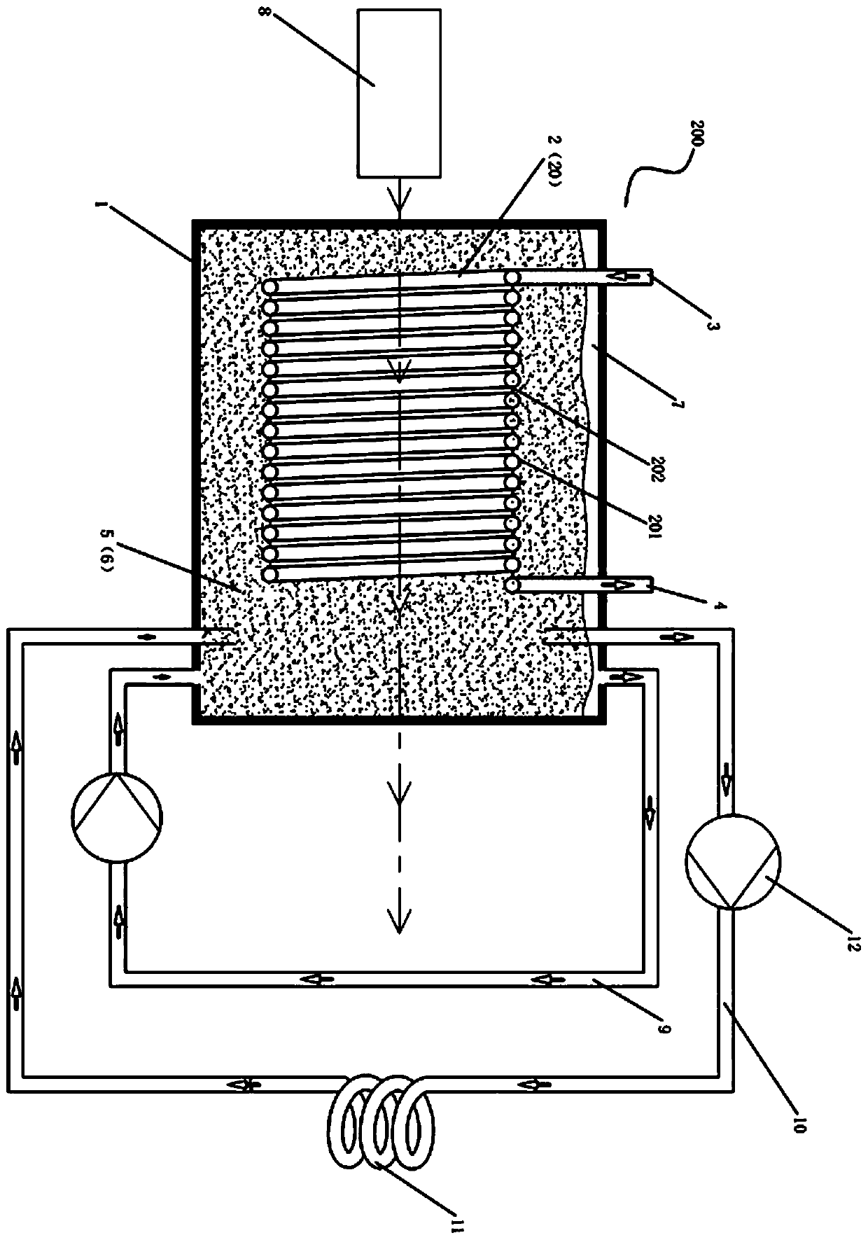
[0036] Such as image 3 A heat supply device 200 for outputting hot oil is shown, which includes: an oil tank cylinder body 1, a spiral coil membrane furnace body 2 in Embodiment 2, a water inlet pipe 3, and a water vapor output pipe 4 , a gas-liquid circulation system 9, a high boiling point liquid heating pipeline 10, a heating module 11, wherein the spiral coil membrane fireplace body 2 includes a furnace 20, the furnace 20 includes a spiral coil 201, a spiral sealing plate 202 , the gap between each helix of the spiral coil 201 is welded with a spiral sealing plate 202, and end plates (not shown in the figure) are welded at both ends of the furnace 20, and the furnace body 2 is placed in the oil tank barrel 1 , A jacket space 5 is formed between the oil tank cylinder body 1 and the furnace body 2, and there is a high-boiling point liquid layer 6 in the jacket space 5, and the high-boiling point liquid layer 6 is composed of a high-boiling point liquid energy-carrying mediu...
PUM
 Abstract
Description
Claims
Application Information
 - R&D Engineer
- R&D Manager
- IP Professional
- Industry Leading Data Capabilities
- Powerful AI technology
- Patent DNA Extraction
Browse by: Latest US Patents, China's latest patents, Technical Efficacy Thesaurus, Application Domain, Technology Topic, Popular Technical Reports.
© 2024 PatSnap. All rights reserved.Legal|Privacy policy|Modern Slavery Act Transparency Statement|Sitemap|About US| Contact US: help@patsnap.com