Eureka AIR delivers breakthrough ideas for toughest innovation challenges, trusted by R&D personnel around the world.

Material transporting mechanism

A technology for conveying mechanisms and materials, applied in the direction of conveyors, conveyor objects, transportation and packaging, etc., can solve the problems of inability to play a role in storage, cumbersome structure, pollution, etc. The effect of sanitation

Pending Publication Date: 2018-01-23
NINGBO KASEEN ECOLOGY TECHNOLOGY CO LTD
View PDF8 Cites 0 Cited by
  • Summary
  • Abstract
  • Description
  • Claims
  • Application Information

AI Technical Summary

Problems solved by technology

Among them, sanitary landfill wastes a lot of land resources, and it is easy to cause pollution to groundwater sources; incineration for power generation can reduce the volume of waste by 50% to 95%, but it is expensive and expensive, and it will release dioxins, mercury, etc. Harmful substances, residual slag and dust are also toxic and harmful, and a large amount of recyclable resources are burned; the composting cycle is long, and organic and inorganic substances need to be separated before they can be recycled
[0006] Before crushing garbage, a material conveying mechanism is required to transport the garbage. At present, the existing material conveying mechanism mainly transports the material through the chain-plate conveyor belt, and then the motor drives the sprocket, rollers, and flat conveyor belt to the bag breaking point. Picking system, this kind of mechanism is the traditional type: the structure is cumbersome, the stability is not strong, the amount of conveyed material is not much, and the water in the material will be leached countercurrently. At the same time, the traditional type consumes a lot of energy, and when a fault is found, it cannot be stored function, it is necessary to manually remove the material and then repair the fault

Method used


Image

  • Material transporting mechanism
  • Material transporting mechanism
  • Material transporting mechanism

Examples


Embodiment Construction

[0038] The specific implementation manners of the present invention will be further described in detail below in conjunction with the accompanying drawings and embodiments. The following examples are used to illustrate the present invention, but are not intended to limit the scope of the present invention.

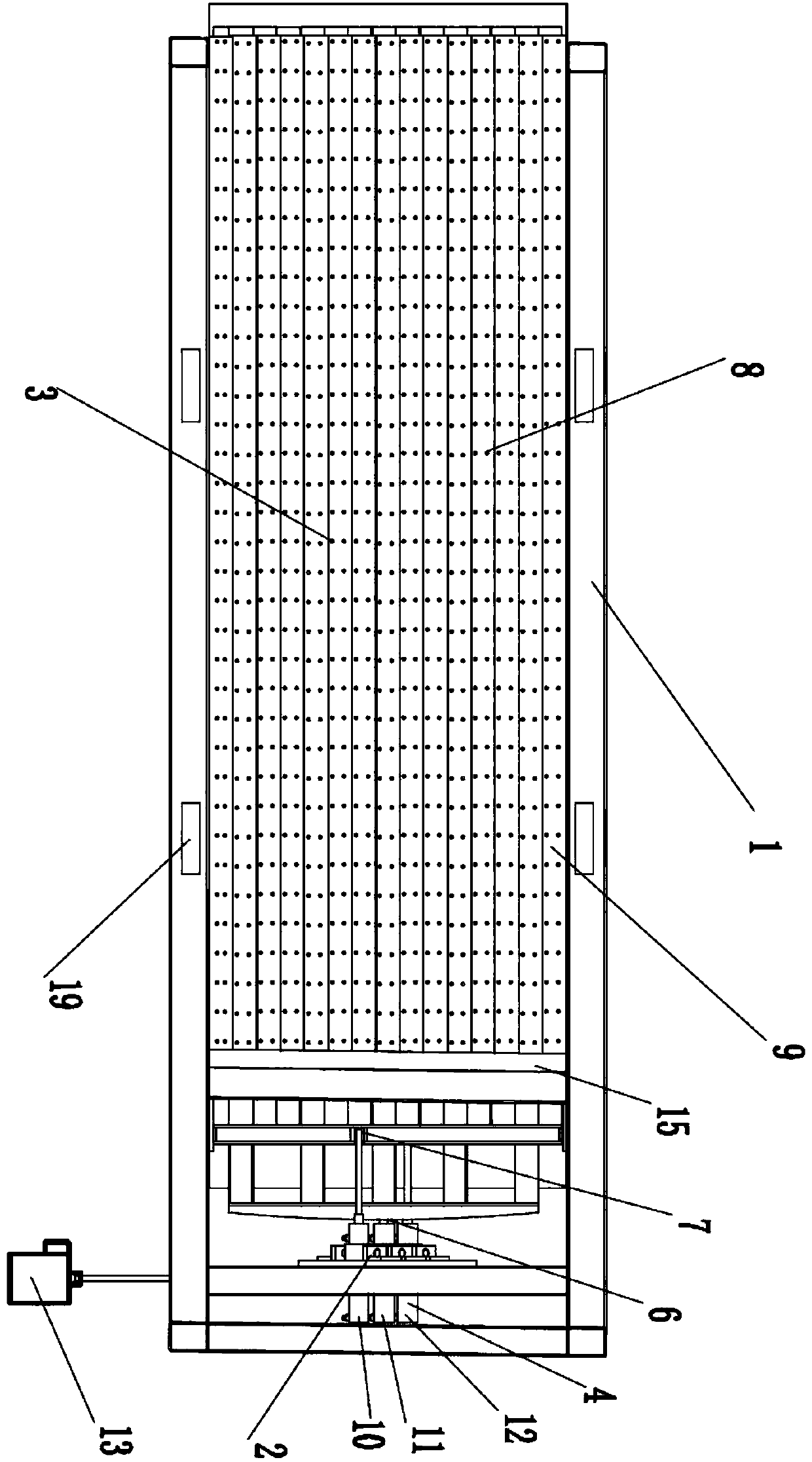
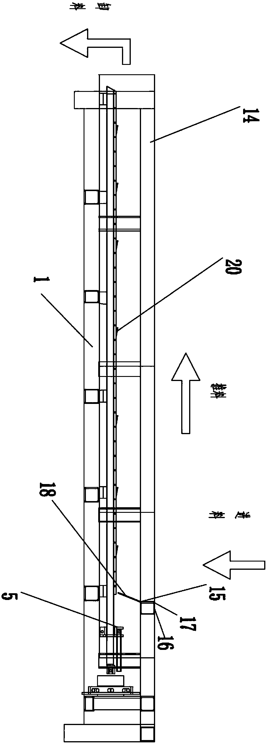
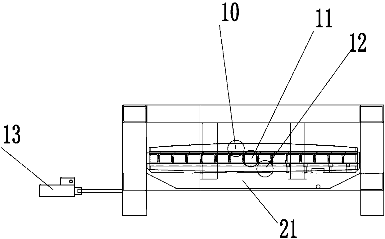
[0039] Such as Figure 1-5 As shown, in order to achieve the above object provided by the present embodiment, the technical solution adopted by the present invention to solve the above technical problem is: a material conveying mechanism, comprising a frame 1, the frame 1 is provided with a pushing assembly 2, a conveying Component 3, hydraulic component 4 and drain collection box 21,

[0040] The pushing assembly 2 includes a first pushing component 5, a second pushing component 6 and a third pushing component 7, and the first pushing component 5, the second pushing component 6 and the third pushing component 7 It is set in a cross dislocation structure;

[0041] The c...


PUM


Abstract

The invention discloses a material transporting mechanism including a frame. The frame is provided with a pushing assembly, a transporting assembly, a hydraulic assembly and a leachate collecting box.The material transporting mechanism not only changes a traditional and inherent thinking frame, and is simple in structure, stable in property and convenient to repair, but also improves the materialtransporting efficiency greatly. Meanwhile, the whole material transporting mechanism is of a semi-closed system and can improve the operation environment hygiene. A panel pushing device is installedat the front end of a bag-breaking machine. The material transporting mechanism and the bag-breaking machine compose a transporting and crushing early sorting system. The material transporting mechanism can be used as independent equipment and also can be arranged as an all-in-one machine. In this way, flexibility is good.

Description

technical field [0001] The invention belongs to the technical field of environmental protection engineering, and in particular relates to a material conveying mechanism. Background technique [0002] With the rapid development of our country's economy, a lot of resources are consumed and a lot of waste is produced, which seriously affects and restricts economic development and threatens people's living quality. Economic development and pollution control have become the consensus of modern society. The direction of environmental protection work is to implement the national development strategy of sustainable development and creating a harmonious society. Environmental protection is a basic state policy of our country. The country has listed the energy-saving and environmental protection industry as one of the seven strategic emerging industries that the country has accelerated its cultivation and development. [0003] According to statistics, in 2011, my country's urban dom...

Claims


Application Information

Patent Timeline
IPC IPC(8): B65G25/08B65G45/22B65G45/26B65B69/00
Inventor 朱华伦郭明龙陈世跃郑勇雷陈春蓬蔡长清毛乾泽
Owner NINGBO KASEEN ECOLOGY TECHNOLOGY CO LTD
Why Eureka
Eureka Blog
Learn More