Steel-fiberglass composite smoke discharging facility

A technology of smoke exhaust facilities and glass fiber reinforced plastics, which is applied in the direction of building types, buildings, towers, etc., can solve problems such as chimney damage, and achieve the effects of reducing project cost, significant economic benefits, and easy processing

Pending Publication Date: 2018-01-23
上海必立结构设计事务所有限公司
View PDF6 Cites 3 Cited by
  • Summary
  • Abstract
  • Description
  • Claims
  • Application Information

AI Technical Summary

Problems solved by technology

[0008] The technical problem to be solved by the present invention is to provide a steel-glass reinforced plastic composite smoke exhaust facility with self-insulation function, meeting the requirements of structural strength and anti-corrosion, and saving engineering cost, which solves the problem of a large number of chimneys due to large-area FGD desulfurization. Problems with varying degrees of damage

Method used


Image

  • Steel-fiberglass composite smoke discharging facility
  • Steel-fiberglass composite smoke discharging facility
  • Steel-fiberglass composite smoke discharging facility

Examples


Embodiment 1

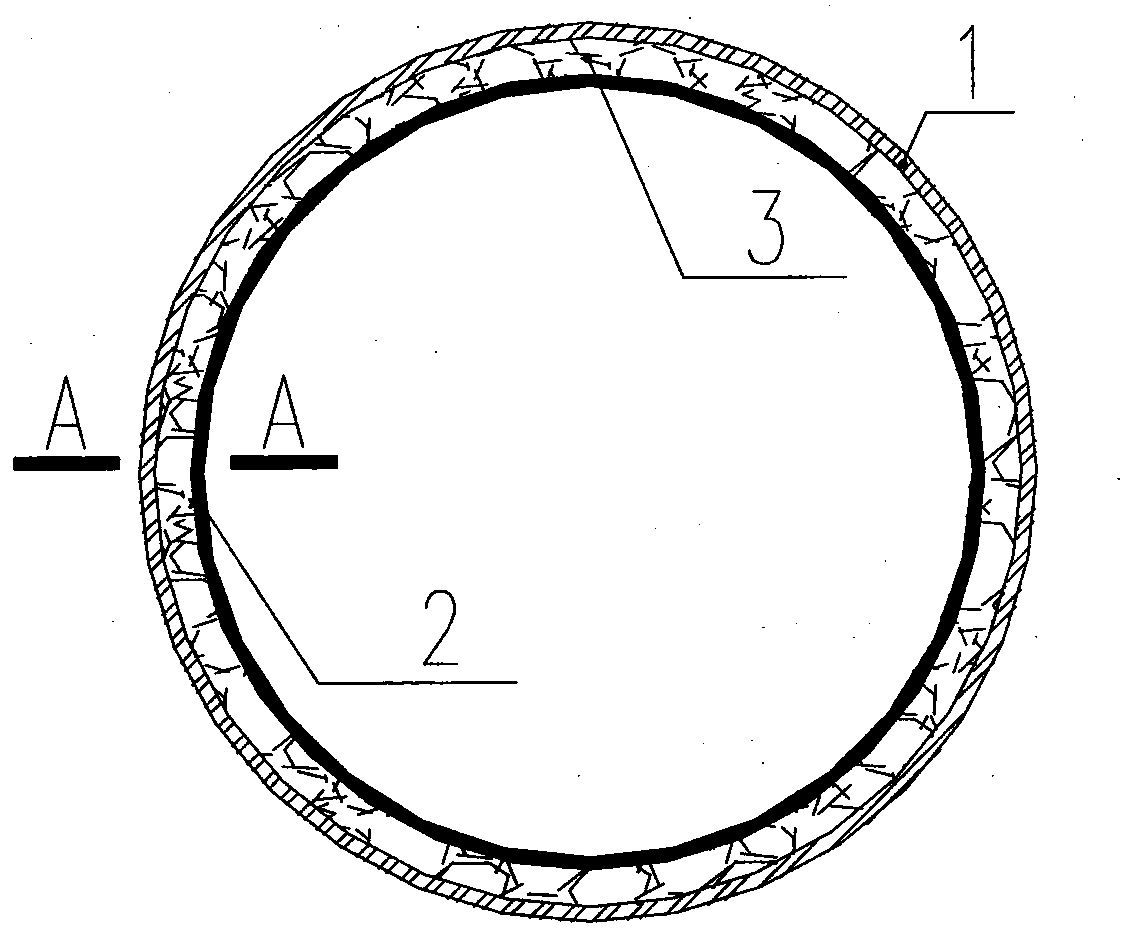
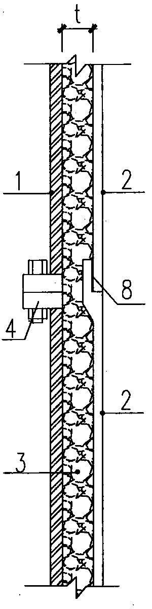
[0032] The present invention relates to a steel-glass reinforced plastic composite smoke exhaust facility. The smoke exhaust facility is a chimney, which is composed of an inner cylinder and an outer cylinder. cylinder, that is, the glass fiber reinforced plastic inner cylinder 2). Such as figure 1 , image 3 As shown, it includes a steel outer cylinder 1 and a fiberglass (FRP) inner cylinder 2, and the diameters of the two cylinders are different; the FRP inner cylinder 2 is arranged in the matching steel outer cylinder 1; the bottom of the FRP inner cylinder 2 is placed on the steel outer cylinder. On the support ring of the cylinder 1; the glass fiber reinforced plastic inner cylinder 2 and the steel outer cylinder 1 pass the polymer foam material 3 to connect the two as image 3 The shown are organically compounded together to form a complex to achieve common force, thereby effectively saving the amount of materials used in the inner and outer cylinders, and realizing th...

Embodiment 2

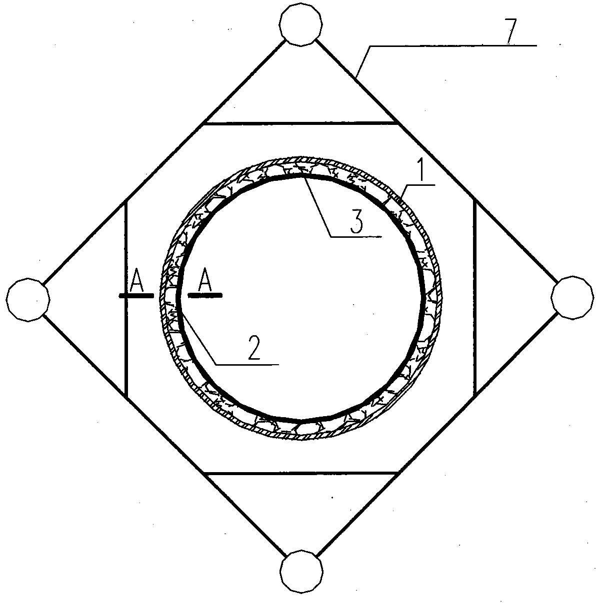
[0039] The composite smoke exhaust facility of the present invention can also adopt the steel tower type, and its plan view is as follows: figure 2 As shown, the outer side of the steel outer cylinder 1 is provided with a steel tower 7. In the case of a tower-type steel chimney, the composite chimney mainly bears the vertical load, and the steel tower 7 mainly bears the horizontal load.

[0040] Others are the same as in Example 1.

Embodiment 3

[0042] In this embodiment, the composite smoke exhaust facility of the present invention can adopt the reinforced concrete sleeve type, and the outer side of the steel outer cylinder 1 is provided with a reinforced concrete outer cylinder 6, and its plan view is as follows Figure 4 , Figure 5 As shown, that is, the composite chimney mainly bears the vertical load, and the horizontal load is mainly borne by the reinforced concrete outer cylinder 6 . The steel outer cylinder 1 is a welded steel cylinder as a whole; the bottom of the glass fiber reinforced plastic inner cylinder 2 is supported by a steel support ring 5 welded on the inner wall of the steel outer cylinder 1, and the glass fiber reinforced plastic inner cylinder 2 is divided into sections by means of sockets. The inner cylinder is connected together; while the glass fiber reinforced plastic 2 and the steel outer cylinder 1 are connected by polymer foam material 3 as Figure 5 The shown are organically combined t...


PUM


Abstract

The invention discloses a steel-fiberglass composite smoke discharging facility. The steel-fiberglass composite smoke discharging facility is characterized in that the steel-fiberglass composite smokedischarging facility comprises a steel outer cylinder and a fiberglass inner cylinder which are different in diameter, the fiberglass inner cylinder is arranged in the steel outer cylinder matched with the fiberglass inner cylinder, and a bearing ring is arranged on the steel outer cylinder; and the bottom of the fiberglass inner cylinder is arranged on the bearing ring, and the steel outer cylinder and the fiberglass inner cylinder are connected in a composite mode through a polymer foaming material. According to the steel-fiberglass composite smoke discharging facility, the structure is simple, joint stress can be achieved, the structure strength requirement is met, and meanwhile the anti-corrosion requirement is met; good heat-preservation performance is achieved, and a heat-preservation layer does not need to be additionally arranged; and the steel-fiberglass composite smoke discharging facility is specially suitable for transformation of an existing steel inner cylinder chimney,the anti-corrosion purpose is achieved by utilizing the existing structure under the premise that the existing steel inner cylinder is not dismounted, thus the engineering manufacturing cost can be greatly reduced, and economic benefits are remarkable.

Description

technical field [0001] The invention relates to a smoke exhaust facility made of composite materials, in particular to a steel-glass reinforced plastic (Steel-FRP Chimney) composite smoke exhaust facility. Background technique [0002] Energy conservation and environmental protection is an important sustainable development policy of the country. At present, my country's air pollutants mainly come from flue gas emissions from industries such as thermal power generation, chemical industry, non-ferrous smelting and metallurgical sintering. The main pollutants in the flue gas are SO2, nitrogen oxides, etc., and the highest content is SO2. Wet flue gas desulfurization (flue-gas desulphurization) is the most widely used desulfurization process in my country. The wet flue gas after wet desulfurization mainly has the following characteristics: [0003] 1) The flue gas temperature is low, about 50°C; [0004] 2) The flue gas has high humidity and is in a saturated state; [0005...

Claims


Application Information

Patent Timeline
Patent Type & Authority Applications(China)
IPC IPC(8): E04H12/28
Inventor 牛春良
Owner 上海必立结构设计事务所有限公司
Why Eureka
Try Eureka