Deep ultraviolet light frequency doubling test device

A test device and deep ultraviolet light technology, applied in the direction of color/spectral characteristic measurement, etc., can solve the problems of attenuator opening cavity, frequent cavity opening, single attenuator setting, etc., to ensure repeatability, comparability, accuracy, The effect of small measurement error

Pending Publication Date: 2018-01-23
TECHNICAL INST OF PHYSICS & CHEMISTRY - CHINESE ACAD OF SCI
View PDF0 Cites 5 Cited by
  • Summary
  • Abstract
  • Description
  • Claims
  • Application Information

AI Technical Summary

Problems solved by technology

[0010] The object of the present invention is to provide a deep ultraviolet light frequency doubling test device, which solves the problem that the deep ultraviolet laser band is easily absorbed by the air through a closed darkroom, and solves the need to replace test samples in a closed darkroom through the movable sample rack and sample control rod The problem of frequent opening of the cavity is solved by setting the light-through block and the light-through hole to solve the problem that the light-through entrance cannot remove stray light. The attenuation plate set and the attenuation control rod are used to solve the problem of single attenuation plate and the transmittance of double-frequency light cannot be adjusted. And the problem of opening the cavity to replace the attenuator

Method used


Image

  • Deep ultraviolet light frequency doubling test device
  • Deep ultraviolet light frequency doubling test device
  • Deep ultraviolet light frequency doubling test device

Examples


Embodiment 1

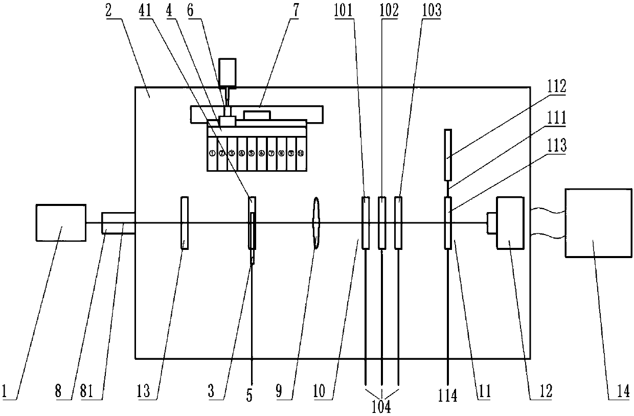
[0049] figure 1 It is a schematic diagram of the test device provided by Embodiment 1 of the present invention;

[0050] Please refer to figure 1 , This embodiment provides a deep ultraviolet light frequency doubling test device, including a light source 1, a closed dark room 2, a sample rack 3, a sample storage 4, and a sample control rod 5.

[0051] Wherein, the light source 1 is arranged at the entrance outside the airtight darkroom 2, and emits ultraviolet light into the airtight darkroom 2 to form a light path. In this embodiment, the light source 1 is an ultraviolet laser light source with a wavelength range of 290-370nm, and the frequency-doubled light generated after irradiating the sample is a deep ultraviolet laser. The wavelength range of the ultraviolet laser band described below is also the wavelength range of the light source 1. The wavelength range is 290nm-370nm, and the wavelength range of the corresponding deep ultraviolet laser, that is, the frequency-doub...

Embodiment 2

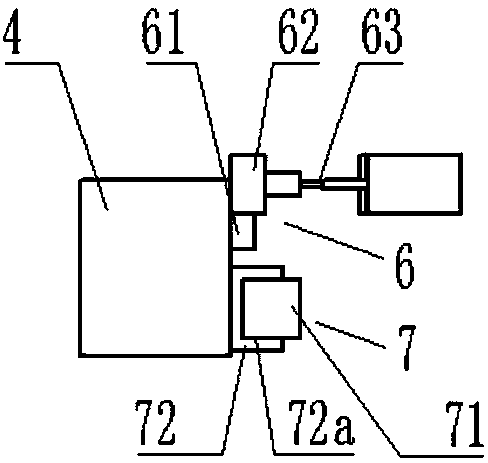
[0094] image 3 It is a schematic diagram of the structure and position of the transmission mechanism and the sliding mechanism provided by the second embodiment of the present invention.

[0095] The difference between this embodiment and the first embodiment lies in that the positions of the transmission mechanism 6 and the sliding mechanism 7 are different.

[0096] Please refer to image 3 , In this embodiment, the rack 61 is arranged on the top surface of the sample library 4 with the tooth surface facing upward. The slide block 72 is arranged on the bottom surface of the sample storage 4, located above the slide rail 71, and is slidably connected with the slide rail 71 through the slide groove 72a. The gear 62 rotates under the drive of the transmission shaft 63, and drives and guides the sample library 4 to move along the slide rail 71 through the rack 61 and the slide block 72, so that the sample boxes 41 of different numbers correspond to the positions of the sample...

Embodiment 3

[0099] The difference between this embodiment and Embodiment 1 or Embodiment 2 is that the sample library 4 is fixed in the airtight darkroom 2 and does not move, and the end of the sample control rod 5 extending out of the airtight darkroom 2 is connected with the control end, and is set to be in the airtight darkroom 2. Move parallel to the optical path under the control of the end.

[0100] In this embodiment, the sliding mechanism 7 is connected to the sample control rod 5, and a second positioning component is arranged on the sliding mechanism 7, so that the sample control rod 5 stops at a preset position during the movement process. The preset position here refers to different When the numbered sample box 41 corresponds to the position of the sample rack 3, the position of the sample control rod 5 is located.

[0101] Specifically, the control terminal controls the sample control rod 5 to move in a direction parallel to the optical path, and the sample control rod 5 driv...


PUM

PropertyMeasurementUnit
lengthaaaaaaaaaa

Abstract

The invention discloses a deep ultraviolet light frequency doubling test device and belongs to the technical field of optical non-linear frequency change. The test device comprises: a light source (1)is arranged at an inlet outside a closed dark room (2), and ultraviolet light emitted by the light source (1) enters the closed dark room (2) to form a light path; the closed dark room (2) a vacuum or nitrogen-filled dark room; a sample rack (3) is movably arranged on the light path in the closed dark room (2); a sample storage (4) is arranged at the position, corresponding to the sample rack (3), of one side of the light path, and accommodates one or more samples; one end of a sample control rod (5) is connected with the sample rack (3), and the other end of the sample control rod (5) stretches out of the closed dark room (2); and the sample rack (3) moves between the sample storage (4) and the light path. The sample rack (3) and the sample control rod (5) are movably provided, so that the samples in the closed dark room (2) can be replaced without opening the room, the measuring error is small, and the repeatability and the comparability of the test result are guaranteed.

Description

technical field [0001] The invention relates to the technical field of optical nonlinear frequency change, and more specifically relates to a deep ultraviolet light frequency doubling test device. Background technique [0002] Optical nonlinear frequency conversion is a technical means to extend the laser frequency, which is of great significance to the development of laser technology and the expansion of laser application fields, and will promote the development of some interdisciplinary and some new fields. [0003] The process of exploring new nonlinear optical materials requires a lot of time and capital investment due to the difficulty of growing single crystals. It is therefore important to somehow be able to first make some estimates of the nonlinear constants of the crystal. The development of powder frequency doubling method is one of the effective methods. [0004] But there is following defect in existing frequency multiplier test device: [0005] 1. Existing t...

Claims


Application Information

Patent Timeline
Patent Type & Authority Applications(China)
IPC IPC(8): G01N21/33
Inventor 宗楠杨峰杨尚彭钦军许祖彦张申金王志敏张丰丰
Owner TECHNICAL INST OF PHYSICS & CHEMISTRY - CHINESE ACAD OF SCI
Why Eureka
Try Eureka