
Bending-resistant single-mode optical fiber and method of making the same

A single-mode fiber, anti-bending technology, applied in the field of optical communication, can solve the problems of low yield, difficult to popularize and apply, cracking of the core layer, etc., to achieve the effect of high yield, convenient manufacturing, and improved bending resistance

Active Publication Date: 2020-06-16
HENGTONG OPTICAL MATERIAL CO LTD +1
View PDF5 Cites 0 Cited by
  • Summary
  • Abstract
  • Description
  • Claims
  • Application Information

AI Technical Summary

Problems solved by technology

For example, CN102998742A invention patent application specification discloses a small mode field bending resistant single-mode optical fiber, which includes a core layer and a cladding layer, the relative refractive index difference Δ1 of the core layer is 0.9%-1.1%, and the radius R1 is 2.4 -3.0μm, the relative refractive index difference Δ2 of the inner cladding is 0%-0.1%, the radius R2 is 9-12μm, and the outer cladding is outside the inner cladding. Use, effectively confine the optical signal to propagate in the core layer, and at the same time, in the bent state, can effectively prevent the optical signal from propagating to the outer layer. From the perspective of optical signal constraint, the bending resistance can be greatly improved. However, Due to the very high doping concentration of germanium in the core layer of this kind of fiber, it is very easy to crack the core layer during the manufacturing process, and the yield is extremely low, so it is difficult to popularize and apply in practice. At the same time, high doping also brings attenuation in the 1550nm window of the fiber Close to 0.3dB / km, much higher than the attenuation level of ordinary G.652D fiber

Method used


Image

  • Bending-resistant single-mode optical fiber and method of making the same
  • Bending-resistant single-mode optical fiber and method of making the same
  • Bending-resistant single-mode optical fiber and method of making the same

Examples


Embodiment Construction

[0029] The present invention will be further described below in conjunction with the accompanying drawings.

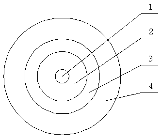
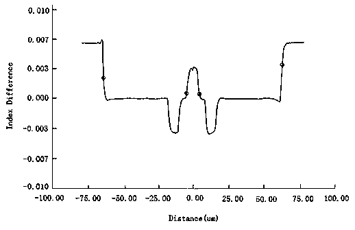
[0030] Such as Figure 1-4 As shown, the bend-resistant single-mode optical fiber involved in the present invention includes a core layer 1 and a cladding layer, the relative refractive index difference of the core layer 1 is greater than that of the cladding layer, and the cladding layer includes an inner cladding layer 2, a sunken cladding layer layer 3 and outer cladding layer 4, wherein the relative refractive index difference of the depressed cladding layer is significantly lower than that of the inner cladding layer and the outer cladding layer, the radius R1 of the core layer is 2.6um, and the relative refractive index difference Δ1 is 0.532 %, the radius R2 of the inner cladding is 7.6um, the relative refractive index difference Δ2 is -0.08%, the radius R3 of the depressed cladding is 15.6um, and the relative refractive index difference Δ3 is -0.45%, the outer ...


PUM

PropertyMeasurementUnit
diameteraaaaaaaaaa
diameteraaaaaaaaaa
radiusaaaaaaaaaa

Abstract

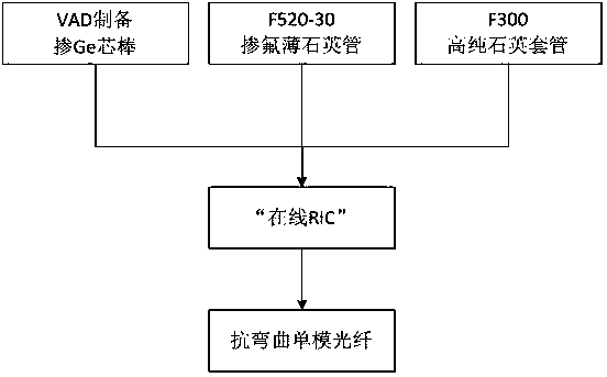
The invention relates to a bending resistant single-mode optical fiber, which comprises a core layer and a cladding layer, and is characterized in that the cladding layer is composed of an inner cladding layer, a downwards sunk cladding layer and an outer cladding layer which are sequentially distributed from the inside out, the core layer adopts germanium-doped quartz glass or germanium-fluorineco-doped quartz glass, the inner cladding layer adopts fluorine-doped quartz glass, the downwards sunk cladding layer adopts fluorine-doped quartz glass, the difference between the relative refractiveindex difference of the core layer and the relative refractive index difference of the inner cladding layer ranges between 0.5% and 0.7%, and the difference between the relative refractive index difference of the core layer and the relative refractive index difference of the downward sunk cladding layer ranges between 0.7% and 1.1%. The invention further relates to a preparation method of the bending resistant single-mode optical fiber, which comprises the steps of preparing a core rod by adopting an axial vapor deposition method, mutually sleeving the core rod, a fluorine-doped thin quartz tube and a high-purity quartz tube to assemble an optical rod used for preparing the optical fiber, and performing high-temperature wiredrawing to prepare the bending-resistance single-mode optical fiber. The optical fiber has good bending resistance, and is convenient to manufacture, high in yield and small in additional loss brought about by bending.

Description

technical field [0001] The invention relates to a bending-resistant single-mode optical fiber, and also relates to a preparation method of the optical fiber. This optical fiber has extremely small bending additional loss, and can be used in optical fiber devices, missile guidance, hydrophones, etc., and belongs to the technical field of optical communication . Background technique [0002] With the rapid development of optical communication technology, single-mode optical fiber has replaced copper wire and has been widely used in short and medium distance control systems. In the process of system integration, people put forward higher and higher requirements for device miniaturization. Therefore, the bending radius of optical fiber It is also required to be smaller and smaller. In a small bending radius, extremely low bending additional loss is a very important requirement, or other problems are brought about in pursuit of the reduction of the bending radius of the optical p...

Claims


Application Information

Patent Timeline
Patent Type & Authority Patents(China)
IPC IPC(8): G02B6/036G02B6/02C03B37/012C03B37/018C03B37/02
Inventor 劳雪刚翟云霄和联科曹兴辉
Owner HENGTONG OPTICAL MATERIAL CO LTD
Learn More