Rotary and rapid elastic releaser and design method thereof

A releaser and elastic technology, which is applied in the field of fast elastic releaser for transmission wire rotation, can solve problems such as tower tilt, threat to safe and stable operation of power grid, and increase in wire sag

Inactive Publication Date: 2018-02-09
HENAN POLYTECHNIC UNIV
View PDF5 Cites 3 Cited by
  • Summary
  • Abstract
  • Description
  • Claims
  • Application Information

AI Technical Summary

Problems solved by technology

[0002] Under the influence of different climatic conditions, transmission lines, especially UHV transmission lines, will have different motion amplitudes and frequencies, mainly high-frequency slight-amplitude breeze vibration, medium-frequency and medium-amplitude sub-gap oscillation, and low-frequency large-amplitude galloping Generally speaking, the movement of transmission wires includes three-degree-of-freedom movements such as horizontal, vertical, and rotation. The initial movement of the wires is a slight vibration near the equilibrium position. , changes from horizontal vibration to vertical vibration, and gradually tends to a certain state of motion, but when the amplitude and rotation reach a certain level, a low-frequency, large-amplitude galloping mainly in the vertical direction is formed, and the galloping increases the sag of the conductor, The axial stress increases and the fatigue limit decreases, which can easily lead to wire breakage; at the same time, the load on the insulator string, cross arm and tower will increase, causing serious disasters such as insulator swing, cross arm deformation, and tower tilting, which pose a threat to the safe and stable operation of the power grid. Great threat, will also directly cause losses to the national economy
[0003] Existing wire movement dampers or releasers have their own advantages and disadvantages: double pendulum damper releasers are suitable for split wires, easy to inst

Method used


Image

  • Rotary and rapid elastic releaser and design method thereof
  • Rotary and rapid elastic releaser and design method thereof

Examples


Embodiment Construction

[0040] Measure and calculate the rotation amplitude and frequency of a region by the MEMS inertial measurement system of the wire movement, and then design the parameters of the elastic release device according to the amplitude-frequency characteristics of the motion, design the structure of the rotation quick release device, manufacture and test the actual object, and the following description is combined with the accompanying drawings The concrete implementation of the present invention.

[0041] The wire motion measurement system is mainly composed of wire motion MEMS inertial measurement system, Zigbee wireless transmission, power supply and monitoring center.

[0042] Due to the rotation of the wire, the angular velocity data collected by the MEMS inertial measurement system has the characteristics of high dimensionality, complexity, dynamics, and high noise. value deviation.

[0043] The measurement of the rotation range of the wire is not measured by calculating the mo...


PUM


Abstract

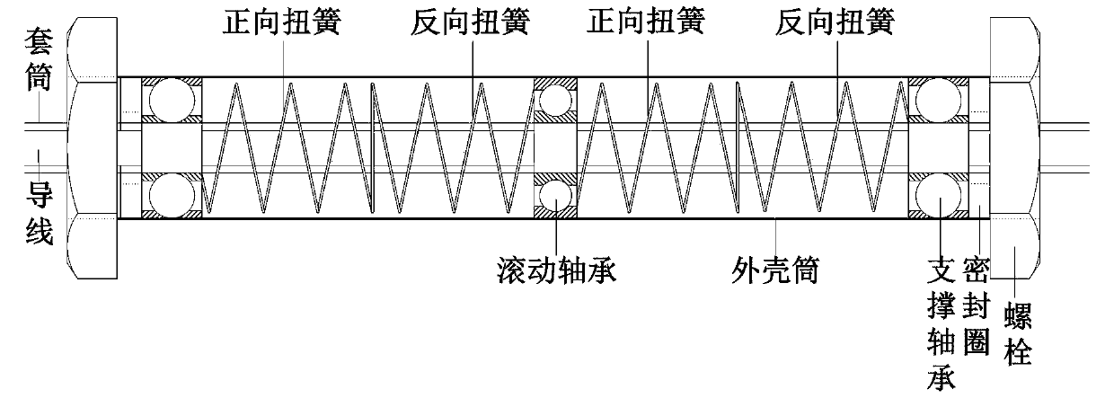
The rotation amplitude and frequency of a wire are measured by an MEMS inertia measurement system, a structure and damping parameters of a releaser are further designed according to the rotation amplitude and frequency and the damping parameters mainly comprise an elastic coefficient of a torsional spring, the length of the torsional spring, the pitch number (the order number represents an n-orderdamper), the mass and the material, a rotary and rapid elastic releaser is further designed. The rotary and rapid elastic releaser comprises an outer shell cylinder, bolts, sealing rings, support bearings, torsional springs, a rolling bearing and a sleeve, wherein a working principle of the rotary and rapid elastic releaser is in a way that rotation energy of the wire is converted to elastic potential energy of the torsional spring, the elastic potential energy is released in a non-oscillation way, the torsional elastic potential energy cannot be returned back to the wire, and an energy release curve of the wire is a single curve with large negative slope. The rotary and rapid elastic releaser is simple in structure, the rotation motion energy of the wire can be particularly and rapidly released, oscillation cannot be generated, and the rotary and rapid elastic releaser is good in stability and has relatively long service lifetime and high application value.

Description

technical field [0001] The invention belongs to the technical safety field of power grid line movement, and in particular relates to a fast elastic releaser for transmission wire rotation and a design method thereof. Background technique [0002] Under the influence of different climatic conditions, transmission lines, especially UHV transmission lines, will have different motion amplitudes and frequencies, mainly high-frequency slight-amplitude breeze vibration, medium-frequency and medium-amplitude sub-gap oscillation, and low-frequency large-amplitude galloping Generally speaking, the movement of transmission wires includes three-degree-of-freedom movements such as horizontal, vertical, and rotation. The initial movement of the wires is a slight vibration near the equilibrium position. , changes from horizontal vibration to vertical vibration, and gradually tends to a certain state of motion, but when the amplitude and rotation reach a certain level, a low-frequency, larg...

Claims


Application Information

Patent Timeline
IPC IPC(8): H02G7/14
CPCH02G7/14
Inventor 杨金显李明奇张国澎冯高明杨明陶慧荆鹏辉
Owner HENAN POLYTECHNIC UNIV
Why Eureka
Try Eureka