
A kind of rotary circulation carbon capture device and method based on three-bed reaction

A carbon capture, rotary technology, applied in separation methods, chemical instruments and methods, dispersed particle separation, etc., can solve the problems of reduced adsorption performance, reduced activity, reduced adsorption capacity, etc., to solve the problem of reduced activity and slow down deactivation , the effect of reducing temperature and energy consumption

Active Publication Date: 2018-11-30
HUAZHONG UNIV OF SCI & TECH
View PDF5 Cites 0 Cited by
  • Summary
  • Abstract
  • Description
  • Claims
  • Application Information

AI Technical Summary

Problems solved by technology

[0008] In view of the above defects or improvement needs of the prior art, the present invention provides a rotating packed bed circulating carbon capture device and method, in which the calcium-based absorbent has reduced pores and severe wear when combined with circulating carbon capture, resulting in its adsorption capacity Therefore, a method and equipment for circulating carbon capture using a rotating packed bed were designed accordingly, and the various processes involved in the circulating carbon capture, as well as the reactor, gas inlet and outlet and other components in the capture device as key components The research and design of the specific structure and layout of the calcium-based absorbent can effectively solve the problems of reduced activity caused by the reduction of pores in calcium-based absorbents, serious wear, and impurities generated by SO2 reactions, and improve the overall reaction rate. It has the advantages of compact equipment, economy and environmental friendliness, so it is especially suitable for the capture of carbon dioxide

Method used


Image

  • A kind of rotary circulation carbon capture device and method based on three-bed reaction
  • A kind of rotary circulation carbon capture device and method based on three-bed reaction

Examples


Embodiment Construction

[0041] In order to make the object, technical solution and advantages of the present invention clearer, the present invention will be further described in detail below in conjunction with the accompanying drawings and embodiments. It should be understood that the specific embodiments described here are only used to explain the present invention, not to limit the present invention. In addition, the technical features involved in the various embodiments of the present invention described below can be combined with each other as long as they do not constitute a conflict with each other.

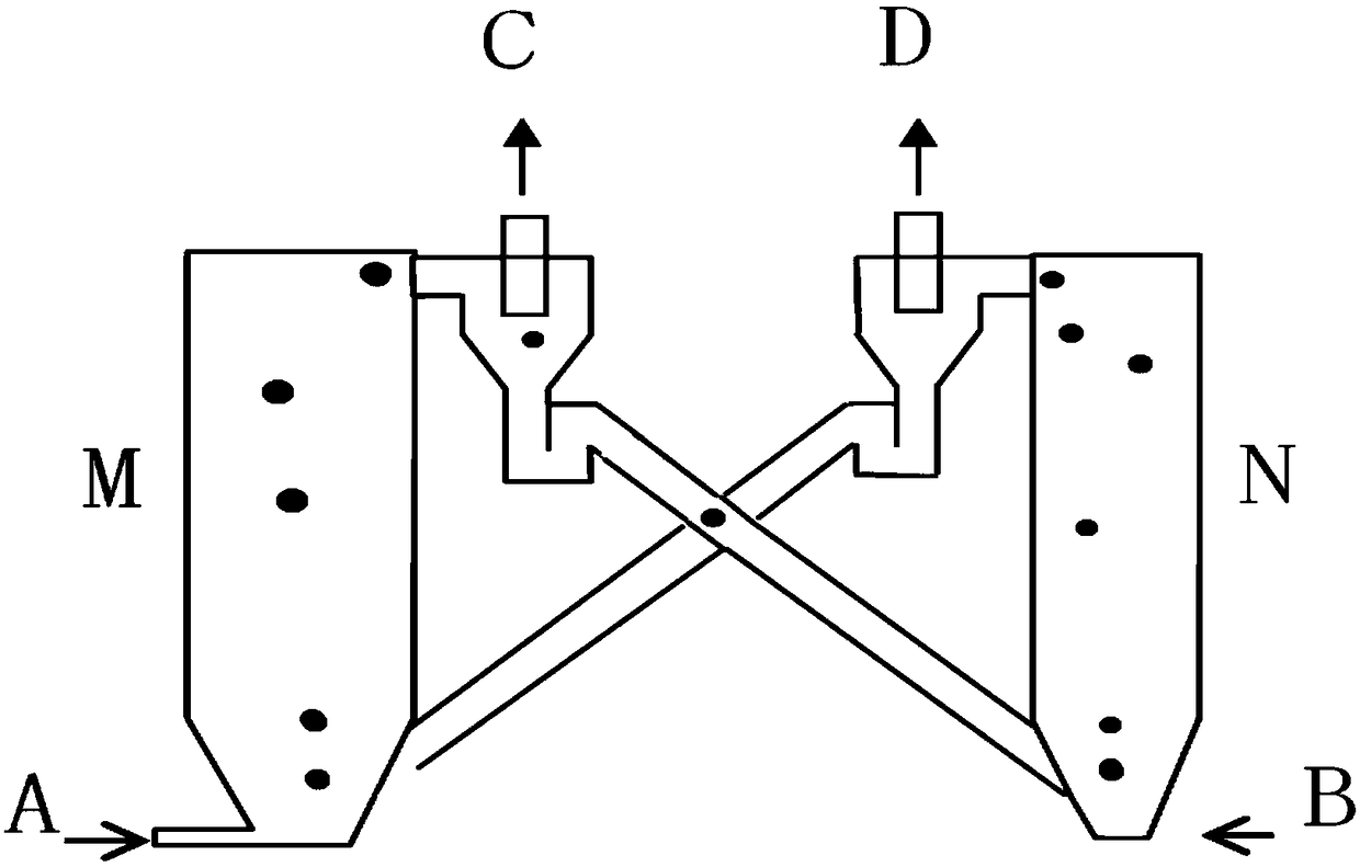
[0042] figure 1 A schematic diagram of the main structure of a fluidized bed system for variable temperature carbon capture based on a solid adsorbent in the prior art is shown. like figure 1 As shown in , in this traditional serial double fluidized bed reactor, the carbonation reactor and the regeneration reactor are arranged separately in different positions of the reaction path, and the sol...


PUM


Abstract

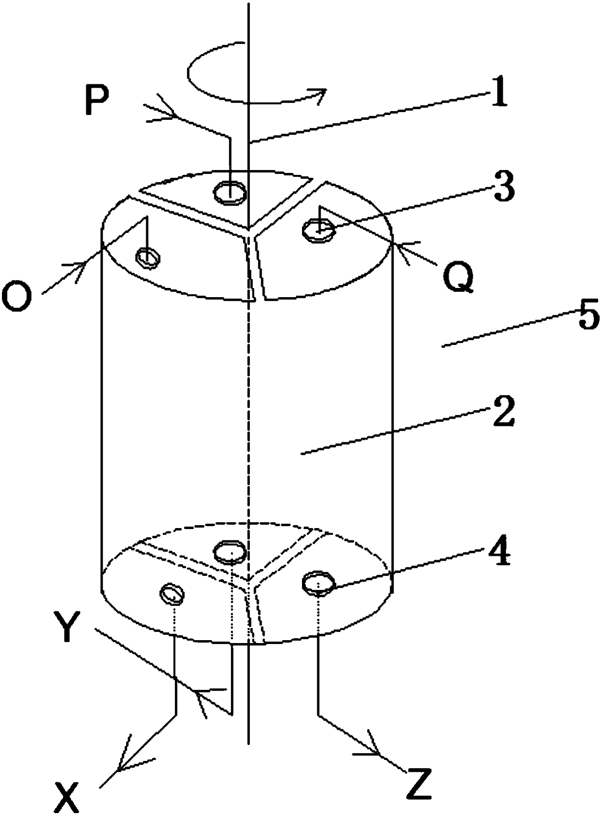
The invention belongs to the field of related equipment of the carbon capture technology and particularly relates to a rotary cyclic carbon capture device and method based on three-bed reaction. The rotary cyclic carbon capture device comprises a rotating shaft and one or more sets of circulatory reaction units, wherein each set of circulatory reaction unit comprises three reactors which are arranged side by side in the circumferential direction of the rotating shaft and are uniformly distributed; a cavity is formed in each reactor and used for placing an absorbent; a gas inlet is formed in the top of each reactor; a gas outlet is formed in the bottom of each reactor; and each gas inlet and the corresponding gas outlet are communicated with the cavity in the corresponding reactor. The invention further discloses a method adopting the rotary cyclic carbon capture device to perform circulatory carbon capture. The problem of adsorption performance degradation caused by the reasons that pores are reduced by high-temperature sintering of a calcium-based absorbent and the pore structures are destroyed by CaSO4 impurities generated by a SO2 reaction is solved, meanwhile, the problem of abrasion of an absorbent is solved, the energy consumption is greatly reduced, and the rotary cyclic carbon capture device is compact in structure and has the advantages of high economical efficiency, excellent environmental friendliness and the like.

Description

technical field [0001] The invention belongs to the field of equipment related to carbon capture technology, and more specifically relates to a rotary continuous circulation carbon capture device and method based on three-bed reaction. Background technique [0002] As we all know, human activities, such as industrial production processes, thermal power plants, cement plants, steel plants, etc., the carbon dioxide emissions formed are the main cause of global warming. CO produced by burning fossil fuels 2 The total amount accounts for about 82% of the total amount of greenhouse gases. As countries around the world pay attention to the global greenhouse effect, reducing carbon dioxide emissions has attracted increasing attention and has become the most important measure for people to deal with global warming. [0003] Many scientific techniques have been proposed to reduce the emission of carbon dioxide gas. At present, the existing carbon dioxide capture methods mainly incl...

Claims


Application Information

Patent Timeline
Patent Type & Authority Patents(China)
IPC IPC(8): B01D53/62B01D53/82B01D53/96
CPCB01D53/62B01D53/82B01D53/96B01D2251/404B01D2251/602B01D2257/504
Inventor 徐勇庆罗聪丁浩然李小珊向霖屹李鹏堃桑会英张立麒
Owner HUAZHONG UNIV OF SCI & TECH
Learn More