Annealing system waste heat recovery device

A waste heat recovery device and annealing technology, used in waste heat treatment, heat treatment furnaces, heat treatment equipment, etc., can solve the problems of uneven temperature distribution, low temperature of preheated workpieces, and low utilization rate of heat energy, and achieve high utilization rate of waste heat. The effect of uniform and high utilization of waste heat

Active Publication Date: 2018-02-13
重庆骏诚机械有限公司
View PDF5 Cites 1 Cited by
  • Summary
  • Abstract
  • Description
  • Claims
  • Application Information

AI Technical Summary

Problems solved by technology

[0004] The purpose of the present invention is to solve the problem that the part of the furnace cavity close to the outlet has a high temperature, while the part of the furnace cavity close to the inlet that needs to be preheated has a lower temperature, a low utilization rate of heat energy and uneven temperature distribution.

Method used


Image

  • Annealing system waste heat recovery device
  • Annealing system waste heat recovery device
  • Annealing system waste heat recovery device

Examples


Embodiment Construction

[0020] The present invention will be described in further detail below through specific embodiments,

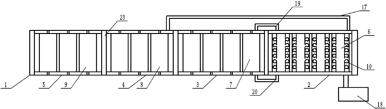
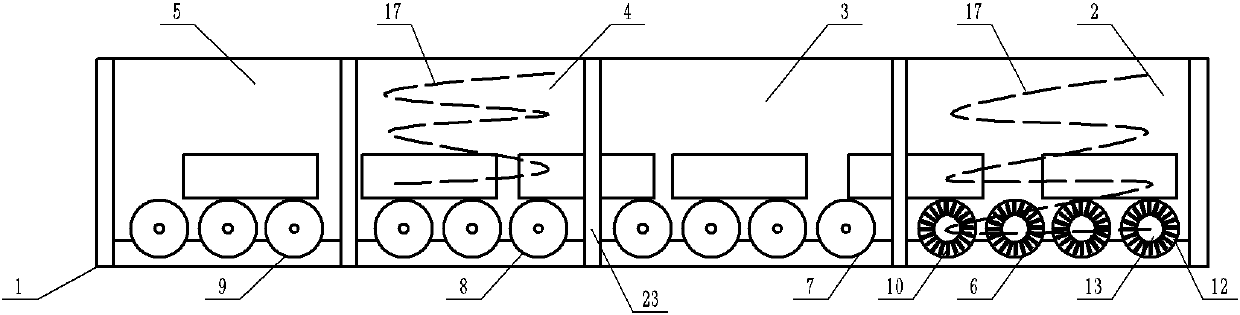
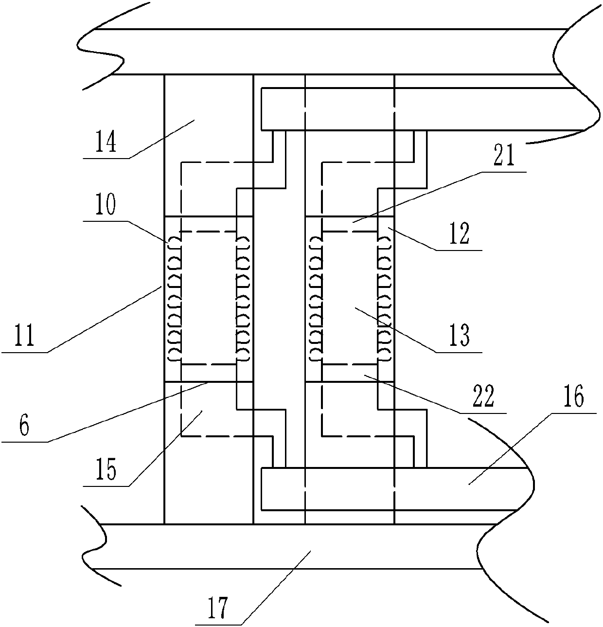
[0021] The reference numerals in the accompanying drawings of the description include: annealing furnace 1, heating section 2, isothermal section 3, slow cooling section 4, normal temperature cooling section 5, first traveling roller 6, second traveling roller 7, third traveling roller 8, Fourth walking roller 9, rotating blade 10, waste heat utilization unit 11, water layer 12, wind layer 13, water pipe 14, air pipe 15, air main pipe 16, water main pipe 17, water pump 18, hot air pipe 19, hot air outlet Pipe 20, air inlet vane 21, air outlet vane 22, insulation door 23.

[0022] Embodiment The waste heat recovery device of the annealing system is basically as attached figure 1 with figure 2 As shown, the waste heat recovery device of the annealing system is set in the annealing furnace 1, including the annealing furnace 1, and the annealing furnace 1 includes a heating se...


PUM


Abstract

The invention belongs to the field of thermal treatment furnaces, and particularly discloses an annealing system waste heat recovery device. The annealing system waste heat recovery device comprises acontrol cabinet and an annealing furnace. A machine frame is arranged at the bottom of the annealing furnace and is further connected with a plurality of moving rollers in a rotating mode. The annealing furnace comprises a warming section, an isothermal section and a slow cooling section which are sequentially arranged. The first moving rollers are provided with air layers and water layers from inside to outside correspondingly. A plurality of rotating blades are circumferentially and evenly distributed on the outer walls of the air layers. Waste heat utilization units comprise air pipes which are connected to the two ends of the air layers in rotating and sealing modes and water pipes which are connected to the two ends of the water layers in rotating and sealing modes. The air pipes penetrate through the corresponding water pipes and are all connected to main air pipes arranged at the two ends of the first moving rollers. According to the scheme, heat in the warming section can be transmitted into the isothermal section and the slow cooling section due to arrangement of the waste heat utilization units in the warming section while workpieces are annealed gradually, the heat in the annealing furnace is utilized, the waste heat utilization rate is high and temperature distribution is made uniform; and moreover automatic matching of the annealing system waste heat recovery device is realized.

Description

technical field [0001] The invention belongs to the field of heat treatment furnaces. Background technique [0002] In the heat treatment furnaces of the prior art, the annealing of discs (bearing steel, spring steel and other discs and round steels) basically adopts well-type furnaces, bell-type furnaces, trolley furnaces or vertical roller furnaces for discharging materials. The biggest disadvantage is high energy consumption and unstable product quality after processing. However, the transmission and transmission stability of vertical roller furnace is poor, and the workpiece is easy to be dumped during processing, resulting in large maintenance and high manufacturing cost. The rack is extremely heavy. [0003] In the heat treatment furnace of the prior art, complete annealing is to be carried out. The furnace body generally includes a heating section, an isothermal section and a slow cooling section. The temperature in the heating section of the furnace body is very hig...

Claims


Application Information

Patent Timeline
Patent Type & Authority Applications(China)
IPC IPC(8): C21D9/54F27D17/00
CPCC21D9/54F27D17/004Y02P10/25
Inventor 娄方银
Owner 重庆骏诚机械有限公司
Why Eureka
Try Eureka