A large dynamic micro current detection circuit
A detection circuit and micro-current technology, applied in the direction of measuring current/voltage, measuring device, measuring electrical variables, etc., can solve the problems of difficult to reach the lower limit of measurement, difficult continuous large dynamic measurement, etc., to achieve low cost, environmental noise suppression, technology good effect
- Summary
- Abstract
- Description
- Claims
- Application Information
AI Technical Summary
Problems solved by technology
Method used
Image
Examples
Embodiment 1
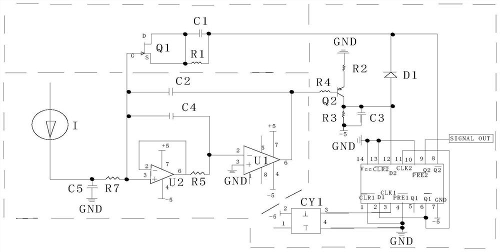
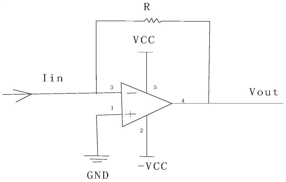
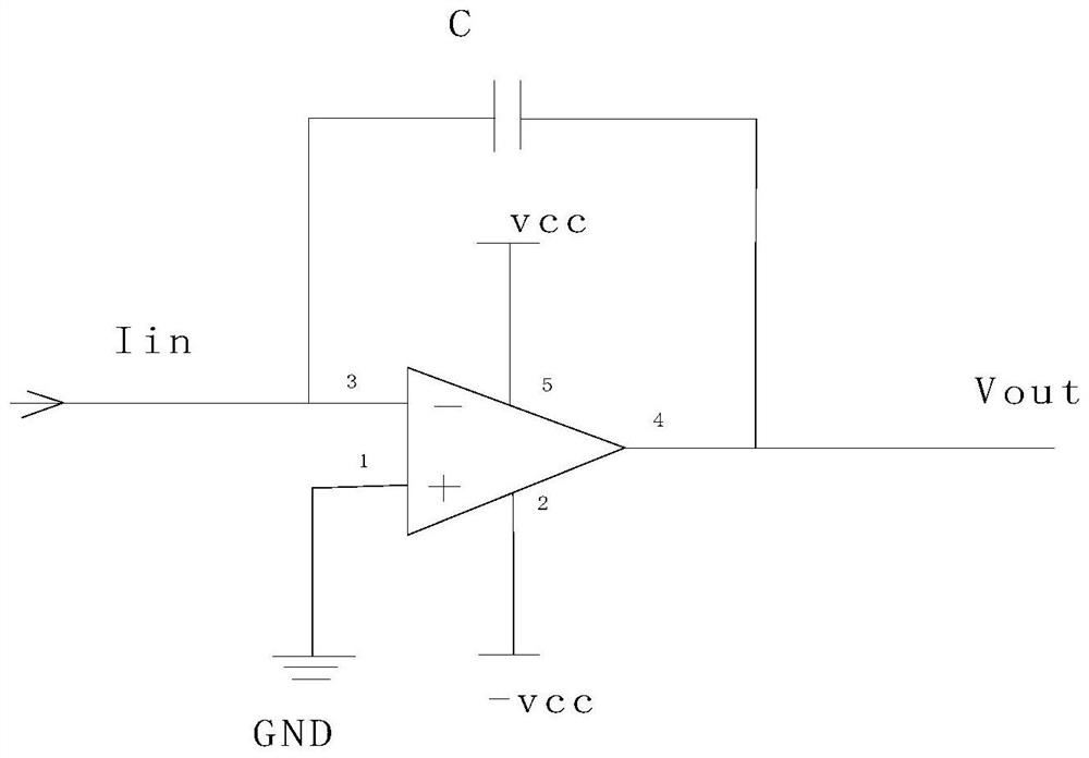
[0026] Such as Figure 1-3 As shown, the present invention includes a large dynamic micro-current detection circuit, including
[0027] Leakage discharge switch circuit: including JFET input impedance Q1, the G pole of Q1 is connected to the non-inverting input terminal of the operational amplifier U2 in the current integration circuit, the D and S poles of Q1 are short-circuited to the left end of capacitor C1 and resistor R1; capacitor C1 and The right ends of the resistor R1 are connected together, and then connected to the K pole of the diode D1 in the charge discharge and frequency generation circuit and the double D flip-flop U3 foot;
[0028] Q1 is an ultra-high input impedance JFET, connect it to a special diode, its reverse saturation current Is is 0.2pA (VGS=-20V), according to the diode equation, the forward current through the diode I=Is(e U / UT -1), U is the diode forward voltage, UT is the temperature voltage equivalent, at normal temperature (300K), UT≈26mV. ...
Embodiment 2
[0034] This embodiment is preferably as follows on the basis of Embodiment 1: the current integration circuit includes operational amplifier U1, operational amplifier U2, resistor R5, resistor R6, resistor R7, capacitor C2, capacitor C4 and capacitor C5, and the left end of resistor R6 is the current input pin, the right end of resistor R6 is connected to the left end of resistor R7; one end of capacitor C5 is connected to the connection point of resistor R6 and resistor R7, and the other end is connected to ground; the right end of resistor R7 is connected to the positive phase input end of operational amplifier U2; operational amplifier U2 The 7-pin is connected to the +5V power supply, and the 4-pin is connected to the -5V power supply; the inverting input terminal and the output terminal are shorted together, and then connected to the left end of the resistor R5; the right end of the resistor R5 is connected to the inverting input terminal of the operational amplifier U1; th...
PUM
 Abstract
Description
Claims
Application Information
 - R&D
- Intellectual Property
- Life Sciences
- Materials
- Tech Scout
- Unparalleled Data Quality
- Higher Quality Content
- 60% Fewer Hallucinations
Browse by: Latest US Patents, China's latest patents, Technical Efficacy Thesaurus, Application Domain, Technology Topic, Popular Technical Reports.
© 2025 PatSnap. All rights reserved.Legal|Privacy policy|Modern Slavery Act Transparency Statement|Sitemap|About US| Contact US: help@patsnap.com


