
Segmented slope compensation circuit applicable to BUCK converter

A technology of slope compensation and converter, applied in electrical components, output power conversion devices, improved amplifiers to improve efficiency, etc., can solve the problems of current mode noise sensitivity, large mismatch, ripple, etc., and achieve the goal of improving accuracy Effect

Active Publication Date: 2018-02-16
UNIV OF ELECTRONIC SCI & TECH OF CHINA
View PDF5 Cites 30 Cited by
  • Summary
  • Abstract
  • Description
  • Claims
  • Application Information

AI Technical Summary

Problems solved by technology

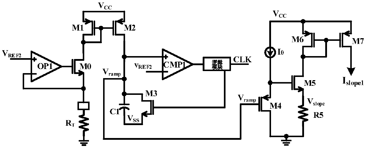
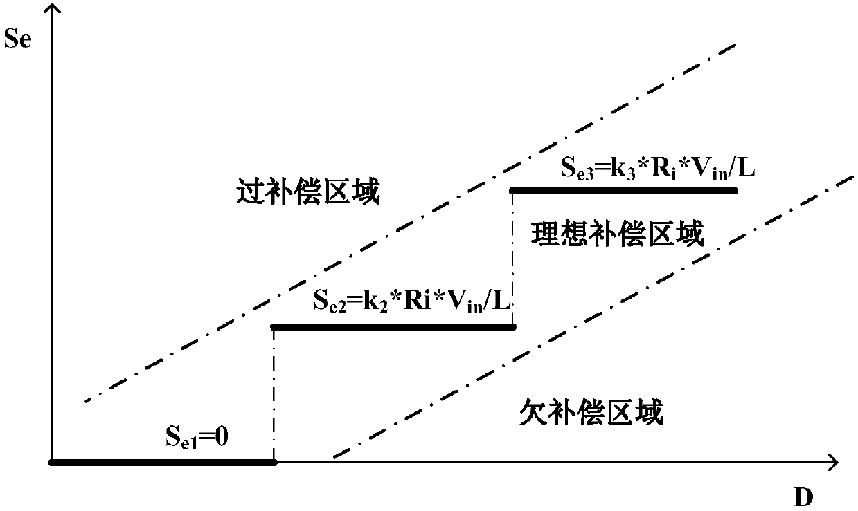
[0007] like figure 1 As shown, in the traditional slope compensation circuit, a single fixed slope is used to compensate the system in all duty cycle conditions. The advantage of this compensation method is that the structure is simple, but the slope m is too small, which will affect the stability of the system, m Too large, easy to overcompensate, reduce the load capacity and transient response speed of the system
At the same time, MOS transistors are used as buffers, and the mismatch is relatively large, which will have a certain impact on the efficiency of the system.
[0008] For the buck converter in voltage mode, although the design is simple, the circuit cost is low and the volume is small, the output regulation response speed of the voltage mode is slow, and the output filter capacitor will bring stability problems to the system; Higher stability and better voltage regulation, but on the other hand, the current mode is very sensitive to noise, especially when the duty cycle is greater than 50%, there may be sub-harmonic oscillation, and the current mode adopts double-loop control , the system design is more complex; although the hysteretic mode and the traditional constant on-time mode have faster transient response, simple control loop and low cost and volume, there are system operating frequency drift and ripple in steady state It is also difficult to meet the high-precision design requirements

Method used


Image

  • Segmented slope compensation circuit applicable to BUCK converter
  • Segmented slope compensation circuit applicable to BUCK converter
  • Segmented slope compensation circuit applicable to BUCK converter

Examples


Embodiment Construction

[0044] The present invention will be described in detail below in conjunction with the accompanying drawings and specific embodiments.

[0045] Such as figure 2 The current feedback control model based on the DC-DC converter is shown, where Tcm is the duty cycle modulation coefficient, Tps is the control amount of the duty cycle to the inductor current, Zcf is the equivalent sampling resistance, and He(s) is the sample and hold Behavior introduces double zeros.

[0046] The appropriate slope compensation can be found through the control-to-output transfer function when the current loop is closed.

[0047]

[0048] Among them, Tcl represents the transfer function of the control loop from the control voltage to the output voltage, Zcf represents the equivalent sampling resistance, s is the frequency term of Laplace, ω n Represents one-half of the switching frequency, ζ represents the damping factor, and there are:

[0049]

[0050] Among them, L is the external inducta...


PUM


Abstract

A segmented slope compensation circuit applicable to a BUCK converter belongs to the technical field of an electronic circuit. An oscillator circuit is used for introducing output voltage informationof the BUCK converter, a negative input end voltage of an operational amplifier is clamped to a positive input end voltage thereof, a first capacitor is charged by a current mirror, the negative inputend voltage, namely a slop voltage signal, of the operational amplifier is obtained, the slop voltage signal is compared with a second reference voltage to obtain a periodic slope voltage signal, a slope current generation circuit is used for generating compensation slopes with different slope rates under different duty ratios, a slope voltage correlated to the duty ratios is generated on a sampling resistor after passing through a slope summing circuit, and a base current compensation circuit is used for stabilizing a system. Compared with a traditional slope compensation circuit, the segmented slope compensation circuit has the advantages that the system stability is improved by employing different slope compensation rates under different duty ratios; and with the adoption of a triode as a buffer, the segmentation accuracy is improved.

Description

technical field [0001] The invention belongs to the technical field of electronic circuits, and in particular relates to a segmented slope compensation circuit for a Buck converter. Background technique [0002] The peak current mode DC-DC converter is prone to sub-harmonic oscillation when the duty cycle D>50%. The slope compensation is the key to ensure the normal operation of the current mode DC-DC converter. Traditional slope compensation proposes to use a fixed slope, which usually results in overcompensation in the case of a small duty cycle, thereby affecting the transient response characteristics and load capacity of the DC-DC converter. [0003] Such as figure 1 The conventional slope compensation circuit shown includes a slope voltage generating circuit and a slope compensation circuit. The non-inverting input terminal of the operational amplifier OP1 is connected to the reference voltage V REF2 , the negative phase input terminal is connected to the source t...

Claims


Application Information

Patent Timeline
IPC IPC(8): H02M1/088H03F1/02
Inventor 明鑫辛杨立胡黎张宣潘溯王卓张波
Owner UNIV OF ELECTRONIC SCI & TECH OF CHINA
Learn More