Linear optical fiber array

An optical fiber array and linear technology, applied in the field of linear image information transmission and linear optical fiber array, can solve the problems of vertical position error, inconsistent slot width, depth error and other problems of the end face of the optical fiber array, and achieve the effect of eliminating horizontal cumulative error

Pending Publication Date: 2018-02-23
INST OF NUCLEAR PHYSICS & CHEM CHINA ACADEMY OF
View PDF9 Cites 5 Cited by
  • Summary
  • Abstract
  • Description
  • Claims
  • Application Information

AI Technical Summary

Problems solved by technology

Multiple adjacent V-shaped grooves are formed on the single crystal silicon substrate, and the bare optical fiber with the coating layer removed is placed in the V-shaped groove, and the radial cross-section of the optical fiber has two points stuck on the side wall of the groove to fix the position of the optical fiber Forming an array, the Chinese patent (patent publication number: CN102692683A) titled "A Fiber Array Positioning Component" discloses a fiber array component that uses silicon V-shaped grooves for positioning. Due to the high positioning accuracy of modern lithography (lithography position The accuracy can reach the nanometer level), and the V-groove fiber array made by this technology has no lateral cumulative error, but affected by the output laser error of the laser head of the lithography machine, the groove formed on the surface of the single crystal silicon plate after photoetching The width of the mouth is often inconsistent, resulting in a large error in the depth of the V-shaped groove after corrosion (the ratio of the width error of the V-shaped groove to the depth error is about 2:3), thus forming the vertical position error of the fiber core on the end face of the fiber array
However, small errors in the lateral position and vertical position of the end face of the fiber array will seriously affect the optical coupling efficiency between the fiber array and the chip or lens array.

Method used


Image

  • Linear optical fiber array
  • Linear optical fiber array
  • Linear optical fiber array

Examples


Embodiment 1

[0031] The upper surface of the bottom plate (1) is successively adjacent to and arranged in parallel with several trapezoidal grooves I (101) with the same structure, the trapezoidal grooves I (101) are isosceles trapezoidal grooves, and the center distances of adjacent trapezoidal grooves are the same;

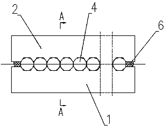
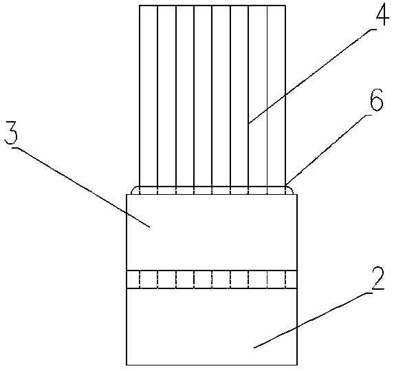
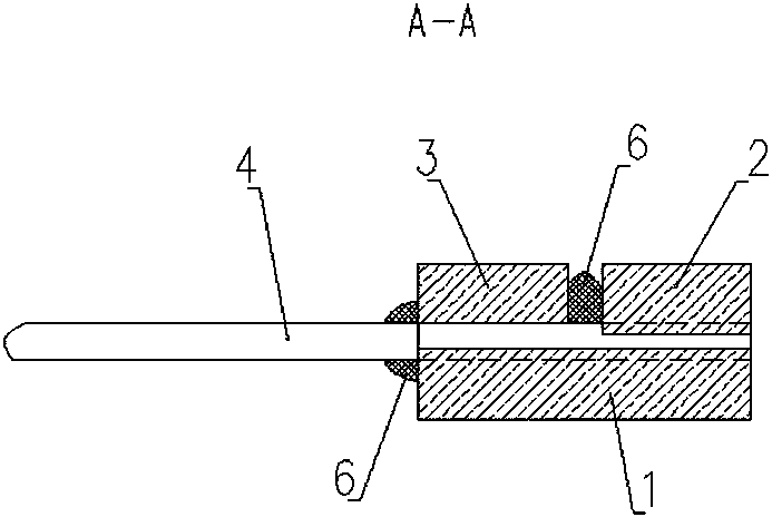
[0032] figure 1 It is the front view of the linear optical fiber array of the present invention, figure 2 is a top view of the linear optical fiber array of the present invention, image 3 for figure 1 A-A direction view in, Figure 4 It is a schematic diagram of the bottom plate structure in the present invention, Figure 5 It is a schematic diagram of the structure of the silicon cover plate in the present invention. exist Figure 1~5 Among them, a linear optical fiber array of the present invention includes a base plate 1, a cover plate above the base plate 1, and several bare optical fibers between the base plate 1 and the cover plate with the coating layer remove...


PUM


Abstract

The invention discloses a linear optical fiber array. The optical fiber array comprises a baseboard, a cover plate, and several strands of bare optical fiber between the baseboard and the cover plate,wherein a coating is removed from the bare optical fiber, the cover plate comprises a silicon cover plate and a glass cover plate, and several trapezoidal grooves which are parallel, densely arrangedat equal intervals and are of the same structure are symmetrically formed in the lower surface of the silicon cover plate and the upper surface of the baseboard. The upper ends and the lower ends ofthe bare fiber are arranged in the corresponding trapezoidal grooves of the silicon cover plate and the baseboard respectively, and are in contact with the bottoms of the trapezoidal grooves. The bareoptical fiber in the trapezoidal grooves in the front end of the baseboard is pressed through the corresponding trapezoidal grooves of the silicon cover plate, and the bare optical fiber in the trapezoidal grooves in the rear end of the baseboard is pressed through the glass cover plate, and therefore each strand of bare optical fiber of the densely arranged optical fiber is jointly located by the corresponding trapezoidal groove and the adjacent optical fiber. By means of the linear optical fiber array, the problem that the precision of locating a fiber core in the optical fiber array utilized during linear image information transmission is solved, vertical offset errors and horizontal cumulative errors of the fiber core in the optical fiber array are avoided, and the linear optical fiber array has the advantages of being high in fiber core locating precision, simple in structure and easy to manufacture.

Description

technical field [0001] The invention belongs to the field of optical fiber information transmission, in particular to a linear optical fiber array for linear image information transmission. Background technique [0002] With the continuous development of optical fibers for information communication, linear optical fiber arrays have been used more and more as a main method of linear image information transmission. Since optical fiber arrays usually need to be coupled with chips or high-precision lens arrays, This involves the positioning accuracy of the optical fiber in the optical fiber array. One of the previous solutions is to rely on the dimensional accuracy of the optical fiber itself, arrange multiple optical fibers closely together, and use two planar materials with high parallelism to place the dense The central axis of each optical fiber end face of the row is controlled in a plane, and the array is formed by extruding both ends of the plane material at the same time...

Claims


Application Information

Patent Timeline
Patent Type & Authority Applications(China)
IPC IPC(8): G02B6/36
CPCG02B6/3636
Inventor 蔡易平章法强李林波魏建民唐文欣杨光玲范娟
Owner INST OF NUCLEAR PHYSICS & CHEM CHINA ACADEMY OF
Why Eureka
Try Eureka