Shutoff energy recovery method and circuit

An energy recovery and circuit technology, applied in the direction of electrical components, high-efficiency power electronic conversion, output power conversion devices, etc., can solve the large turn-off loss of the main switch tube, increase the turn-off loss of the auxiliary switch tube, and unfavorable power module miniaturization and other issues to achieve the effect of reducing loss

Inactive Publication Date: 2018-02-27
MORNSUN GUANGZHOU SCI & TECH
View PDF4 Cites 5 Cited by
  • Summary
  • Abstract
  • Description
  • Claims
  • Application Information

AI Technical Summary

Problems solved by technology

[0005] (1) The turn-off loss of the main switch tube is large, which is not conducive to the miniaturization of the power module;
[0006] (2) Although the turn-off loss of the main switch is reduced by connecting a capacitor in parallel to the main switch, this method will affect the turn-on process of the switch, increase the turn-off loss of the auxiliary switch tube, and increase the zero-voltage turn-on time. difficulty

Method used


Image

  • Shutoff energy recovery method and circuit
  • Shutoff energy recovery method and circuit
  • Shutoff energy recovery method and circuit

Examples


no. 1 example

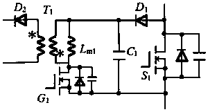
[0035] figure 2 It is a schematic diagram of the first embodiment of the turn-off energy recovery circuit of the switch of the present invention, wherein the unidirectional conduction module is composed of a diode D1, the energy storage module is composed of a capacitor C1, the energy feedback module is a DC-DC converter, and the DC-DC The converter is composed of a flyback circuit. The flyback circuit includes a transformer T1, a primary circuit formed by the primary winding of the transformer T1, and a secondary circuit formed by the secondary winding of the transformer T1; the primary circuit of the flyback circuit also includes The switch G1, the secondary side circuit also includes a diode D2.

[0036] The connection relationship of the first embodiment of the turn-off energy recovery circuit of the switch of the present invention is as follows:

[0037] The anode of the diode D1 is taken as the first input terminal of the shutdown energy recovery circuit, which is used...

no. 2 example

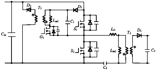
[0050] The principle diagram of the second embodiment is the same as that of the first embodiment, but the control method is different. The switch G1 and the switch S1 are turned on at the same time, but the turn-on time of the switch G1 is fixed. After the switch G1 is turned on, the excitation inductance Lm1 releases energy to the power supply terminal through the diode D2. The working principle differs from that of the first embodiment in that the on-off sequence method is different, and the process of the diode D1 freewheeling the current of the exciting inductor Lm1 is removed, but the final result is the same, and will not be repeated here.


PUM


Abstract

The invention provides a shutoff energy recovery method and circuit. The shutoff energy recovery circuit comprises a capacitor C1, a diode D1 and a DC-DC converter; the DC-DC converter is composed ofa flyback circuit, and the flyback circuit comprises a transformer T1, a primary circuit formed by primary winding of the transformer T1 and a secondary circuit formed by secondary winding of the transformer T1; an anode of the diode D1 is led out to serve as a first input end of the shutoff energy recovery circuit and used for being connected with one end of a power switch tube; a cathode of thediode D1 is connected with a positive electrode of the capacitor C1, and a negative electrode of the capacitor C1 is led out to serve as a second input end of the shutoff energy recovery circuit and used for being connected with the other end of the power switch tube; the two ends of the capacitor C1 are connected with the primary circuit of the flyback circuit, and an output end of the secondarycircuit of the flyback circuit is led out to serve as an output end of the shutoff energy recovery circuit and used for being connected with an external power supply end.

Description

technical field [0001] The invention relates to a method and a circuit for recovering energy when a switch is turned off, in particular to a method and a circuit for recovering the energy when a main switching tube of an asymmetrical half-bridge flyback circuit is turned off. Background technique [0002] The main switching tube (that is, the power switching tube) of the existing asymmetrical half-bridge flyback circuit is used as an electronic switch (hereinafter referred to as a switch), and when it is turned on or off, loss will occur in the overlapping region of voltage and current. The traditional method is generally to modify the circuit parameters to reduce the switching loss. This method has poor generality. Since the excitation current of the asymmetrical half-bridge flyback circuit can be reversed, it can realize zero-voltage turn-on, thereby reducing the turn-on loss. However, the main power transistor of the asymmetric half-bridge flyback circuit has a large cu...

Claims


Application Information

Patent Timeline
Patent Type & Authority Applications(China)
IPC IPC(8): H02M1/34
CPCH02M1/34H02M1/0058Y02B70/10
Inventor 王志燊尹向阳
Owner MORNSUN GUANGZHOU SCI & TECH
Why Eureka
Try Eureka