High-power ultrasonic transducer with controllable sound field

An ultrasonic transducer and high-power technology, applied in ultrasonic therapy, fluid using vibration, treatment, etc., can solve the problems of small range of sound waves, uncontrollable sound field, limited power capacity, etc., to improve power capacity and increase power Capacity and sound radiation efficiency, effect of increasing power capacity

Pending Publication Date: 2018-03-06
CHINA JILIANG UNIV
View PDF5 Cites 9 Cited by
  • Summary
  • Abstract
  • Description
  • Claims
  • Application Information

AI Technical Summary

Problems solved by technology

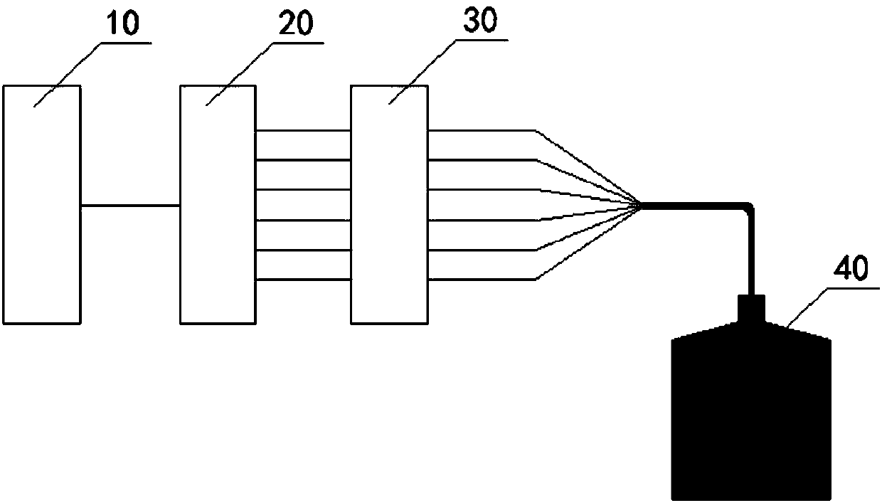
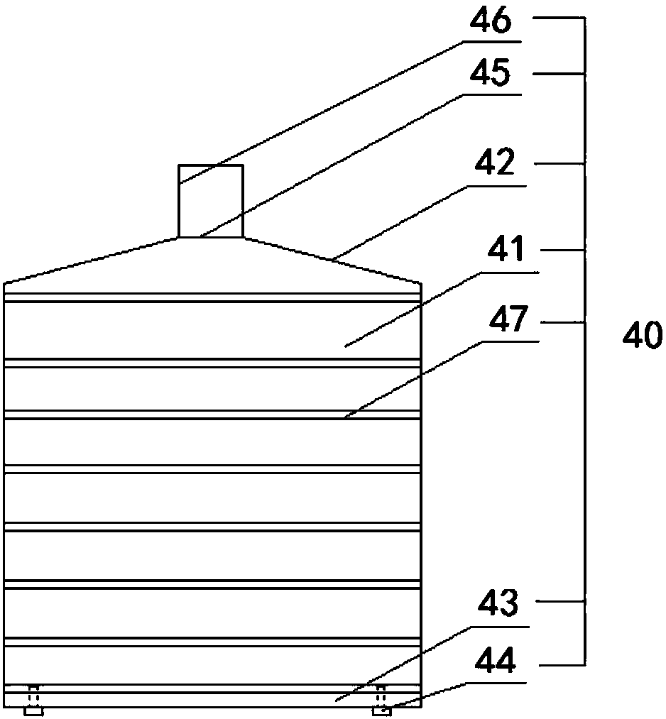
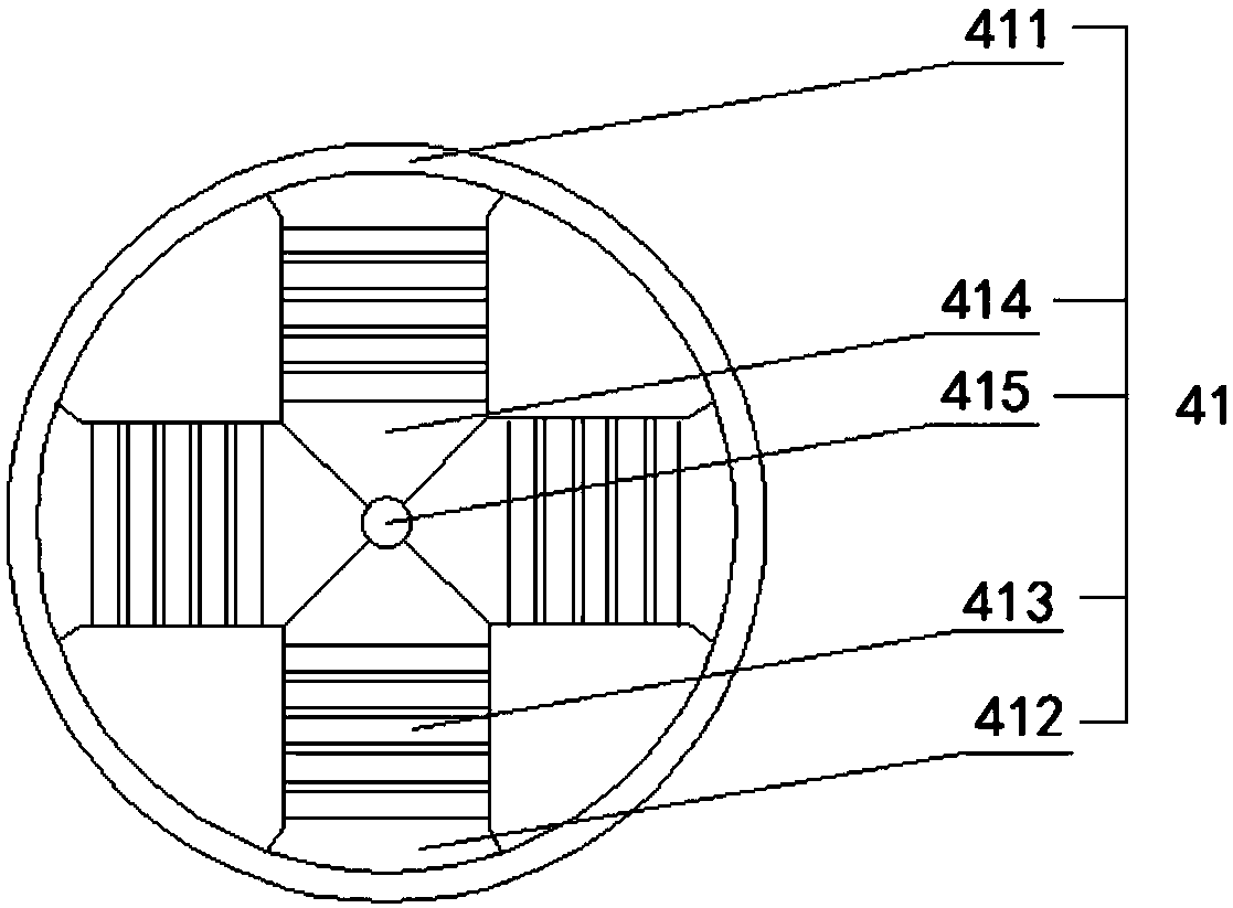
[0005] The purpose of the present invention is to provide a high-power ultrasonic transducer with controllable sound field to solve the problem of limited power capacity, low sound radiation efficiency, and small sound range of a single longitudinal vibration sandwich piezoelectric ultrasonic transducer existing in the prior art. The sound field cannot be adjusted and other technical problems, and the high-power ultrasonic transducer with controllable sound field provided by the present invention divides the oscillating voltage provided by the ultrasonic frequency power supply into several multi-channel signals with a certain phase difference through the signal delay system, and the multi-channel power The amplifier then amplifies the signals of each channel, and excites each compound-driven piezoelectric ultrasonic tubular transducer unit, and realizes the dynamic regulation of the sound field by changing the phase difference of the excitation signal, which can be used in detection ultrasound, power ultrasound, medical ultrasound, etc. Real-time regulation of the size of the focus area of ​​the circular sound field in three-dimensional space, the radius of the focus ring, and the position of the focus in the axial direction

Method used


Image

  • High-power ultrasonic transducer with controllable sound field
  • High-power ultrasonic transducer with controllable sound field
  • High-power ultrasonic transducer with controllable sound field

Examples


Embodiment Construction

[0043] The technical solutions of the present invention will be clearly and completely described below in conjunction with the accompanying drawings. Apparently, the described embodiments are some of the embodiments of the present invention, but not all of them. Based on the embodiments of the present invention, all other embodiments obtained by persons of ordinary skill in the art without making creative efforts belong to the protection scope of the present invention.

[0044] In the description of the present invention, it should be noted that unless otherwise specified and limited, the terms "installation", "connection" and "connection" should be understood in a broad sense, for example, it can be a fixed connection or a detachable connection. Connected, or integrally connected; it may be mechanically connected or electrically connected; it may be directly connected or indirectly connected through an intermediary, and it may be the internal communication of two components. ...


PUM


Abstract

The invention provides a high-power ultrasonic transducer with a controllable sound field. The high-power ultrasonic transducer with the controllable sound field comprises an ultrasonic frequency power source, a signal delay system, a multi-channel power amplifier and a linear array composite drive piezoelectric ultrasonic pipe-shaped transducer. Oscillating voltage provided by the ultrasonic frequency power source is divided by the signal delay system into a plurality of multi-channel signals with the certain phase difference, the multi-channel power amplifier amplifies the multi-channel signals and excites composite drive piezoelectric ultrasonic pipe-shaped transducer units, the sound field is dynamically adjusted by changing the phase difference of excitation signals, the defects thata single longitudinal vibration sandwich type piezoelectric ultrasonic transducer is limited in power capacity, low in acoustic radiation efficiency, small in sound wave acting range and incapable ofadjusting the sound field are overcome, the three-dimensional space circular ring-shaped sound field focusing area size, focusing circular ring radius and the position of a focus point in the axial position can be adjusted in real time in the application fields of detection ultrasound, power ultrasound and medical ultrasound.

Description

technical field [0001] The invention relates to the technical field of ultrasonic transducers, in particular to a high-power ultrasonic transducer with controllable sound field. Background technique [0002] With the continuous innovation of ultrasonic technology and the continuous improvement of application level, power ultrasonic has been widely used in industrial and agricultural production, medical and health, biopharmaceutical and food processing and other fields. Ultrasonic transducer is the core component of ultrasonic processing equipment, and its performance directly determines the application effect of power ultrasound. [0003] At present, the transducers widely used in ultrasonic processing equipment are longitudinal vibration sandwich piezoelectric transducers. Because this type of transducer has simple structure, stable performance, and has the advantages of large power capacity and high electromechanical conversion efficiency. However, with the continuous de...

Claims


Application Information

Patent Timeline
Patent Type & Authority Applications(China)
IPC IPC(8): B06B1/06A61N7/00
CPCA61N7/00B06B1/0625
Inventor 许龙李凤鸣
Owner CHINA JILIANG UNIV
Why Eureka
Try Eureka