Array antenna optimization method for effectively controlling dynamic range of excitation amplitude

A technology of excitation amplitude and dynamic range, applied in design optimization/simulation, special data processing applications, complex mathematical operations, etc., can solve the problems of low excitation dynamic range, lack of universality, easy overfitting, etc. Calculate solution time, high performance of calculation results, and reduce the effect of unknown variables

Active Publication Date: 2018-03-06
JINLING INST OF TECH
View PDF6 Cites 6 Cited by
  • Summary
  • Abstract
  • Description
  • Claims
  • Application Information

AI Technical Summary

Problems solved by technology

[0004] Previous solutions to this problem mainly focused on global optimization algorithms, such as adaptive parameter control and adaptive particle swarm optimization for evolutionary state updates. Compared with classical particle swarm optimization, adaptive particle swarm optimization has a more efficient Search efficiency, but with the increase in the number of unknowns, the amount of calculation increases sharply, and the global search algorithm shows inherent slow convergence speed, easy over-fitting, falling into the local optimal solution instead of the global optimal solution, etc., resulting in antenna The radiation performance is not optimal and cannot effectively control the dynamic range of the excitati

Method used

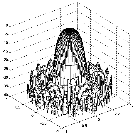
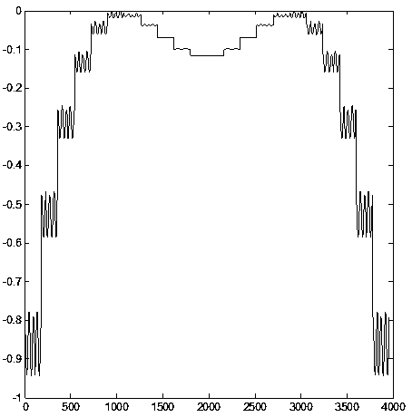
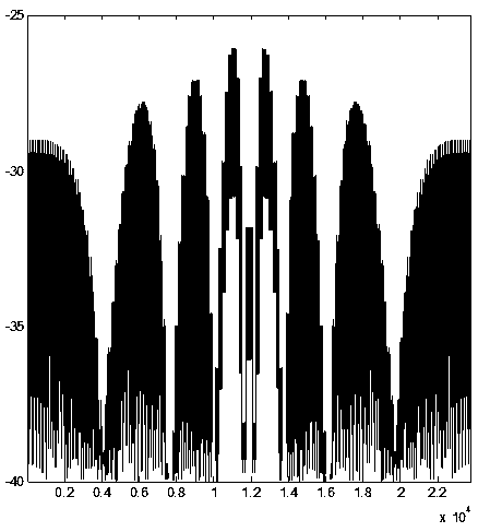

Image

  • Array antenna optimization method for effectively controlling dynamic range of excitation amplitude
  • Array antenna optimization method for effectively controlling dynamic range of excitation amplitude
  • Array antenna optimization method for effectively controlling dynamic range of excitation amplitude

Examples


Embodiment Construction

[0047] Below in conjunction with accompanying drawing and specific embodiment the present invention is described in further detail:

[0048] The invention provides an array antenna optimization method for effectively controlling the dynamic range of the excitation amplitude. The invention uses the Fourier transform algorithm to study a fast synthesis method for the array pattern. The core idea of ​​the algorithm is to calculate the Antenna array element excitation, and then use the convex optimization algorithm to calculate and obtain the array element excitation with the characteristics of small excitation amplitude dynamic range corresponding to the radiation performance. In the hybrid optimization method in the present invention, the traditional IFT algorithm is improved and the excitation amplitude constraint condition is added. , in the part of the convex optimization algorithm, the calculation results of the IFT algorithm are fully utilized, thereby avoiding the shortcomi...


PUM


Abstract

The invention discloses an array antenna optimization method for effectively controlling a dynamic range of excitation amplitude. Wave beams of different radiation requirements are realized in a relatively small excitation dynamic range; unit excitation corresponding to a directional graph meeting radiation performance requirements is obtained by using an improved iterative Fourier algorithm; units of a maximum part and a minimum part of the excitation amplitude are determined; an excitation complex value of the unit of the minimum part of the excitation amplitude is subjected to phase preservation and amplitude direct assignment processing; the obtained excitation complex value serves as a part of a final complex excitation vector of an antenna; and a complex excitation value of the unitof the residual part is searched for by utilizing an improved convex optimization algorithm to meet the radiation performance index requirements of the directional graph. The relatively small dynamicchange range of the complex excitation amplitude of the antenna can effectively simplify a feed network to reduce the feeder line cost, and the mutual coupling between the units can be well controlled; and the application range of the method is not limited to special preconditions such as excitation complex value conjugate symmetry, array element central symmetry layout, array element equal interval or the like.

Description

technical field [0001] The present invention relates to the field of array signal processing, in particular to a method for effectively controlling excitation amplitude dynamics [0002] Array Antenna Optimization Method for Range. Background technique [0003] With the development of modern radar technology, the system has higher and higher requirements for antenna performance. Array antennas are often used in many phased array radars, and the sidelobes of the antennas are often required to be as low as possible to achieve a good spatial filtering effect, thereby effectively improving the signal-to-noise ratio of the radar front-end signal. In order to obtain low or ultra-low sidelobes for conventional phased array antennas, the dynamic range of the excitation amplitude of the elements in the array aperture will inevitably be too large, resulting in extremely demanding requirements for the machining accuracy of the antenna and feed system. Therefore, the dynamic range exci...

Claims


Application Information

Patent Timeline
IPC IPC(8): G06F17/50G06F17/14
CPCG06F17/142G06F30/20
Inventor 田小敏杨忠司海飞
Owner JINLING INST OF TECH
Why Eureka
Try Eureka