Optical signal sending system, receiving system, method and communication system

A technology of sending system and receiving system, which is applied in the field of communication and can solve the problems of high bandwidth requirements, large space occupation, and large power consumption.

Inactive Publication Date: 2018-03-06
ZTE CORP
View PDF1 Cites 25 Cited by
  • Summary
  • Abstract
  • Description
  • Claims
  • Application Information

AI Technical Summary

Problems solved by technology

[0005] The main technical problem to be solved by the embodiments of the present invention is to provide an optical signal transmission system, a receiving system and method, and a communication system, which solve the problem of the large number of transceiver devices and space constraints in the existing large-capacity and short-distance optical communication systems in the prior art. Large footprint, large transceiver device size, high power consumption, high bandwidth requirements, and high system cost

Method used


Image

  • Optical signal sending system, receiving system, method and communication system
  • Optical signal sending system, receiving system, method and communication system
  • Optical signal sending system, receiving system, method and communication system

Examples


Embodiment 1

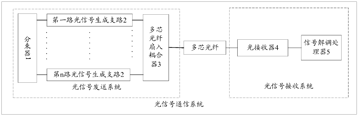
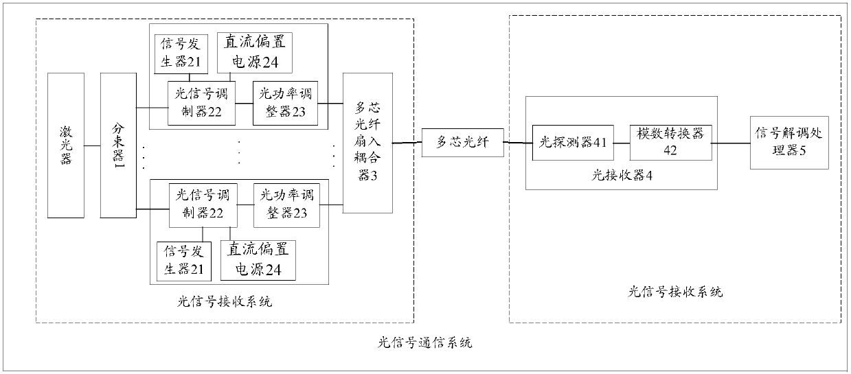
[0031] see figure 1 , the present embodiment provides an optical signal communication system, the transmitting end uses only one laser, utilizes multiple independent channels provided by the multi-core optical fiber, and realizes parallel transmission of multiple signals with different powers at the same wavelength in the multi-core optical fiber; at the receiving end Only one optical detector is used to receive multiple signals at the same time, and after analog-to-digital conversion, the serial interference elimination demodulation method is used to serially demodulate signals with different powers; finally, the sending and receiving of multiple signals is completed, and the overall transmission is improved. capacity, can effectively reduce system costs, meet the cost requirements for short-to-medium-distance large-capacity transmission, and provide a better short-to-medium-distance large-capacity transmission system.

[0032] The advantages of using multi-core optical fiber...

Embodiment 2

[0075] see Figure 4 , showing a method for sending an optical signal, including:

[0076] S401. Dividing the laser signal from the light source into n paths of laser sub-signals and inputting them into n paths of optical signal generation branches respectively;

[0077] S402. After loading the electrical signal to be sent on each optical signal generation branch to the laser sub-signal received by each optical signal generation branch and modulating it into an optical signal, send it to the optical signal through the corresponding n optical channels in the multi-core optical fiber. In the signal receiving system, the power of the optical signal output by each optical signal generating branch is different.

[0078] In this embodiment, the light source is generally a laser light source, and based on the above-mentioned system of this embodiment, only one laser light source may be used in this embodiment. Among them, in order to reduce the impact of laser phase noise on the tr...

Embodiment 3

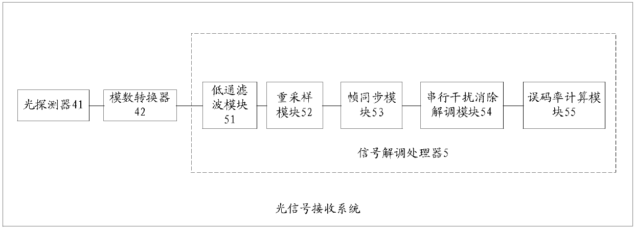
[0089] see Figure 5 , this embodiment shows a method for receiving an optical signal, including:

[0090] S501. Receive and process n optical signals sent by the optical signal transmission system through n optical channels in the multi-core optical fiber, where n is greater than 1, and the powers of the n optical signals are different;

[0091] S502. Based on the different powers of the n channels of optical signals, demodulate each channel of optical signals through serial interference cancellation demodulation to obtain n channels of demodulated signals.

[0092] In this embodiment, the optical detector is generally used to receive n optical signals transmitted in the multi-core optical fiber. Generally, in order to simultaneously detect the optical signals on N parallel branches in the multi-core optical fiber, preferably, the optical signal used in this embodiment The photodetector should be a photodetector with a large photosensitive surface, and the diameter of its ef...


PUM


Abstract

The invention discloses an optical signal sending system, a receiving system, a method and a communication system. According to the invention, laser signals from a light source can be divided into a plurality of channels of laser sub-signals. The to-be-sent electric signal of each branch of all optical signal generating branches is loaded to the laser sub-signal of the branch to be modulated, andthen various optical signals different in power are formed. The signals are transmitted to an optical signal receiving system through multi-core optical fibers. Based on different powers of all branches of optical signals, the optical signal receiving system modulates the optical signals through the serial demodulation process so as to obtain signals respectively transmitted through all optical signal generating branches. According to the invention, the requirement on the hardware number of a transceiving system is low, and the usage of an active photoelectric device is reduced. The cost, thespace and the power consumption of the system are reduced. The parallel transmission of multi-channel data is realized through multi-core optical fibers, and the space utilization rate and the totaltransmission rate of the system are improved. Through adopting the serial demodulation, the correct demodulation of multi-channel signals is realized. The frequency spectrum efficiency of the system is improved. The invention is particularly suitable for the large-capacity and short-and-intermediate-distance communication transmission.

Description

technical field [0001] The invention relates to the field of communication, in particular to an optical signal sending system, a receiving system and method, and a communication system. Background technique [0002] The emergence of new applications and services such as mobile Internet, cloud computing, high-definition video-on-demand, and virtual reality has enabled Internet data traffic to maintain rapid growth. The rapid growth of network traffic has brought huge expansion pressure to existing communication networks and information transmission systems, and the emergence of new services has changed the distribution of network traffic and even the network architecture. Research by Cisco and Bell Labs shows that the traffic of short- and medium-distance MANs has surpassed that of long-distance backbone networks, and continues to grow at twice the growth rate of backbone network traffic. In addition, traffic services in the MAN are constantly shifting to the data center. I...

Claims


Application Information

Patent Timeline
Patent Type & Authority Applications(China)
IPC IPC(8): H04B10/50H04B10/69H04B10/2581
CPCH04B10/2581H04B10/503H04B10/697
Inventor 李蒙吴少勇
Owner ZTE CORP
Why Eureka
Try Eureka