

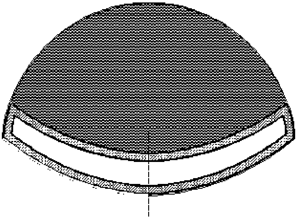
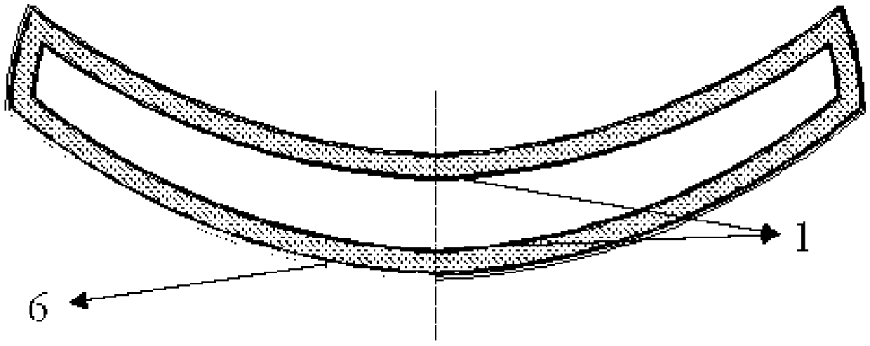
High-temperature-resistant air intake passage with both radar stealth and infrared stealth and preparation method thereof
A radar stealth and air intake technology, which is applied to the combustion of the air intake of the power unit, the arrangement/installation of the power unit, and the assembly of the aircraft, etc. The problem of high infrared emissivity of stealth coating can solve the problems of radar stealth and infrared stealth, with strong designability and high working temperature.
- Summary
- Abstract
- Description
- Claims
- Application Information
AI Technical Summary
Problems solved by technology
Method used
Image

Examples
Embodiment 1
[0038] Step 1: Prepare the wave-absorbing and bearing-integrated layer and the electromagnetic shielding layer
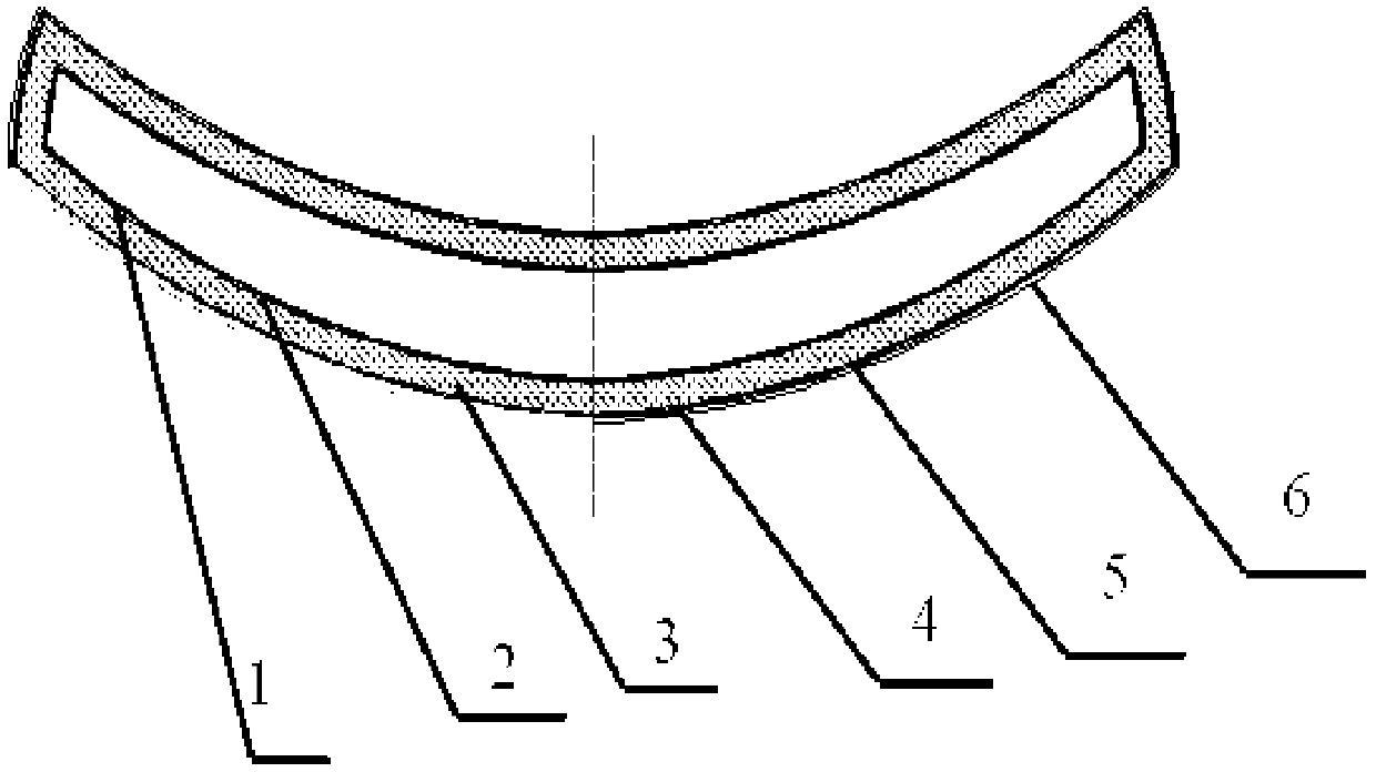
[0039] The wave-absorbing SiC fiber (the real part of the dielectric constant is 14-20) and T300 carbon fiber (the electrical conductivity is about 50000S / m) are selected to weave according to the inlet model, and the rough blank is prepared by fiber impregnation and pyrolysis (PIP). After the braid has sufficient strength and toughness, it is machined according to the shape of the air inlet model to obtain an integrated wave-absorbing and bearing layer and an electromagnetic shielding layer.
[0040] The second step: post-densification treatment and fine machining
[0041] Carry out five cycles of conventional ceramic precursor impregnation and pyrolysis process (PIP) to convert the product obtained in the first step from an open-cell structure to a closed-cell structure, stop after the air inlet does not increase in weight, and then perform precise machining. Mak...
Embodiment 2
[0051] Step 1: Prepare the absorbing and bearing integrated layer
[0052] SiN fiber (dielectric constant real part 3-8) is used as matching layer (thickness is 1.3mm), SiC fiber (dielectric constant real part is 16-20) is used as absorbing layer (thickness is 2.8mm), T300 carbon fiber ( The electrical conductivity is about 50000S / m) as the electromagnetic shielding layer (thickness is 0.15mm), integrated weaving is carried out according to the air inlet model, and the rough blank is prepared by fiber impregnation and pyrolysis process (PIP), and the woven piece has sufficient strength and toughness Finally, machining is carried out according to the shape of the inlet model to obtain the wave-absorbing and bearing-integrated layer and the electromagnetic shielding layer.
[0053] The second step: post-densification treatment and fine machining
[0054] Carry out six cycles of conventional ceramic precursor impregnation and pyrolysis process (PIP) to convert the product obtain...
Embodiment 3
[0064] Step 1: Prepare the wave-absorbing and bearing-integrated layer and the electromagnetic shielding layer
[0065] Select wave-absorbing SiC fibers (the real part of the dielectric constant is 12-20) and shielding SiC fibers (conductivity is about 50S / m) to weave according to the inlet model, and use the fiber impregnation and pyrolysis process (PIP) to prepare rough blanks , after the braid has sufficient strength and toughness, it is machined according to the shape of the inlet model to obtain the wave-absorbing and bearing-integrated layer and the electromagnetic shielding layer.
[0066] The second step: post-densification treatment and fine machining
[0067] Carry out five cycles of conventional ceramic precursor impregnation and pyrolysis process (PIP) to convert the product obtained in the first step from an open-cell structure to a closed-cell structure, stop after the air inlet does not increase in weight, and then perform precise machining. Make its shape cons...
PUM
| Property | Measurement | Unit |
|---|---|---|
| Thickness | aaaaa | aaaaa |
| Conductivity | aaaaa | aaaaa |
| Thickness | aaaaa | aaaaa |
Abstract
Description
Claims
Application Information