Disc and plate strip structure-based composite laser amplifier

A laser amplifier and slab structure technology, applied in the laser field, can solve the problems of low power, low laser energy, and poor beam quality, and achieve the effects of energy extraction, high flexibility, high amplification efficiency, and output light quality

Inactive Publication Date: 2018-03-23
HUAZHONG UNIV OF SCI & TECH
View PDF5 Cites 0 Cited by
  • Summary
  • Abstract
  • Description
  • Claims
  • Application Information

AI Technical Summary

Problems solved by technology

[0003] In view of the above defects or improvement needs of the prior art, the present invention provides a composite laser amplifier based on a disc and slab structure, thereby solving the problem of low laser energy, low power and beam quality output by the existing disc solid-state laser amplifier. poor technical issues

Method used


Image

  • Disc and plate strip structure-based composite laser amplifier
  • Disc and plate strip structure-based composite laser amplifier
  • Disc and plate strip structure-based composite laser amplifier

Examples


Embodiment 1

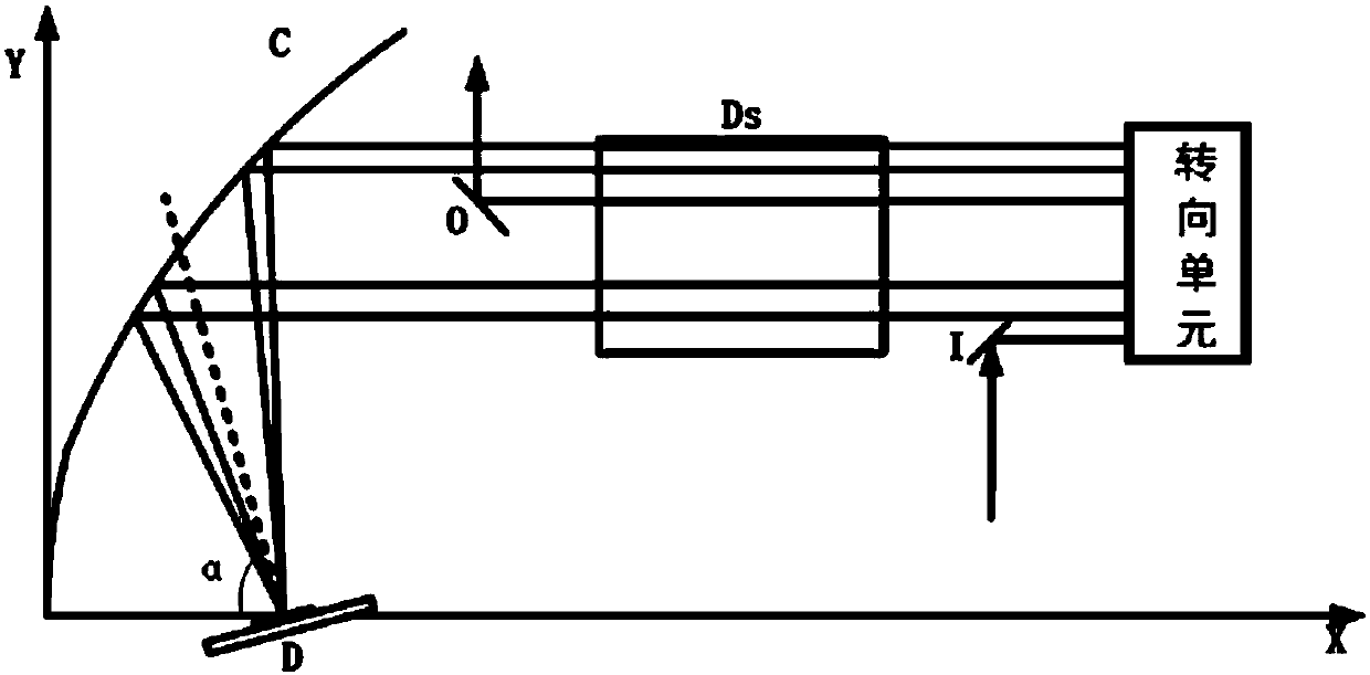
[0067] Figure 6 It is the schematic plan view of the structure of the disk laser amplifier of embodiment 1, comprising disk crystal D, slab crystal Ds, rectangular prism M, parabolic mirror surface C and incident and outgoing unit I, O; the focal point of parabolic mirror is positioned at the center of disk crystal place; the front of the disc crystal has an anti-reflection film, and the back has a total reflection film; its back is oppositely provided with a parabolic reflector for reflecting the output pump light to the back of the disc crystal. By selecting the pump module inside the disc crystal, the spot size of the pump light can be made to be the same as that of the seed light. When the active particles inside the disc crystal absorb the pump light, they transition from the ground state to the excited state, and then under the action of the seed light, stimulated radiation occurs between the energy levels of the active particles, so that the energy of the seed light is...

Embodiment 2

[0072] Figure 8 It is a schematic plan view of the disk laser amplifier of Example 2. Except that the right-angle prism is replaced by a parabolic mirror and a disc crystal, the rest of the device structure is the same as that of Embodiment 1. It is worth noting that although the parabolic mirror C1 and the disc crystal D1 are mirror-symmetrical to the parabolic mirror C2 and the disc crystal D2, there must be one difference in the angle of the disc crystal or the upper and lower positions of the parabolic mirror, otherwise the seed light will enter the laser amplifier. It can only repeat the trajectory of one route, and cannot fully utilize the lath-shaped crystals, nor can it achieve multiple amplifications of the seed light.

[0073] Figure 9 It is the structural space schematic diagram of the disk laser amplifier of embodiment 2, we can obtain the specific propagation route of seed light as:

[0074] I→C2→D2→C2→Ds→C1→D1→C1→Ds→C2→D2→C2

[0075] →Ds→C1→D1→C1→Ds→C2→D2→C...


PUM


Abstract

The invention discloses a disc and plate strip structure-based composite laser amplifier. The composite laser amplifier comprises an incidence unit, a steering unit, plate strip-shaped crystals, a first objective lens, first disc crystals and an outgoing unit; the incidence unit is used for reflecting the incident seed light into parallel light rays; the steering unit is used for performing 180-degree steering on the parallel light rays reflected by the incidence unit; the plate strip-shaped crystals are used for amplifying the steered parallel light rays; the first objective lens is used forenabling the parallel light rays amplified by the plate strip-shaped crystals to be focused to emit to the first disc crystals; the first disc crystals are used for enabling the light rays focused andincident by the first objective lens to be amplified and reflected to the first objective lens so as to be reflected by the first objective lens to form parallel light rays; and the outgoing unit isused for reflecting the seed light which satisfies the preset amplifying requirement out of the composite laser amplifier. By virtue of the composite laser amplifier, the technical problems of low laser energy, low power and relatively poor light beam quality output by the existing disc solid laser can be solved.

Description

technical field [0001] The invention belongs to the field of laser technology, and more specifically relates to a composite laser amplifier based on a disc and slat structure. Background technique [0002] Disk solid-state laser amplifier is a high-end solid-state laser amplifier. The essential difference between it and traditional laser amplifiers lies in the shape of the laser working material. Disk solid-state laser amplifiers do not use traditional rod-shaped crystals but choose to use very thin thickness, about It is a disc crystal with a diameter of 0.2mm to 0.4mm and a diameter of about 5mm to 30mm. A large amount of heat will be generated during the working process of the amplifier. Excessive waste heat will cause thermally induced birefringence in the crystal gain medium of the amplifier, causing thermal distortion of the laser, and further deterioration after the laser passes through the amplifier for many times, and finally reduces the output laser energy. , powe...

Claims


Application Information

Patent Timeline
Patent Type & Authority Applications(China)
IPC IPC(8): H01S3/10H01S3/102
CPCH01S3/10007H01S3/1022
Inventor 朱广志顾标平余金波朱晓王海林
Owner HUAZHONG UNIV OF SCI & TECH
Why Eureka
Try Eureka