Check patentability & draft patents in minutes with Patsnap Eureka AI!

Ultrashort light pulse source applicable to photoelectric analog-digital conversion

A technology of analog-to-digital conversion and ultra-short light, applied in optical analog/digital converters, optics, circuits, etc., can solve problems such as complex structure, difficult multi-wavelength output, and electrostatic sensitivity of optical pulse sources, and achieve the effect of simple structure

Inactive Publication Date: 2018-03-30
BEIJING INST OF REMOTE SENSING EQUIP
View PDF4 Cites 2 Cited by
  • Summary
  • Abstract
  • Description
  • Claims
  • Application Information

AI Technical Summary

Problems solved by technology

[0003] The purpose of the present invention is to provide an ultra-short optical pulse source suitable for photoelectric analog-to-digital conversion, which solves the problems of electrostatic sensitivity, complex structure and difficulty in multi-wavelength output in the existing optical pulse source

Method used


Image

  • Ultrashort light pulse source applicable to photoelectric analog-digital conversion

Examples


Embodiment 1

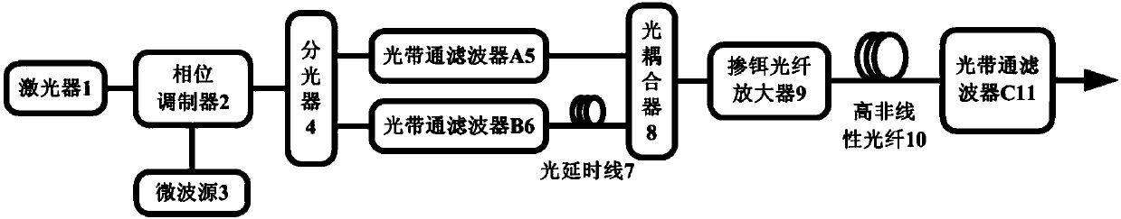
[0013] An ultrashort optical pulse source suitable for photoelectric analog-to-digital conversion, comprising: a laser 1, a phase modulator 2, a microwave source 3, an optical splitter 4, an optical bandpass filter A5, an optical bandpass filter B6, and an optical delay Line 7, optical coupler 8, erbium-doped fiber amplifier 9, high nonlinear fiber 10 and optical bandpass filter C11.

[0014] The microwave source 3 is connected to the microwave input port of the phase modulator 2, the laser 1 is connected to the optical input port of the phase modulator 2, and the optical output port of the phase modulator 2 is connected to the input port of the optical splitter 4; the optical splitter 4 has two Output ports, wherein one of the output ports is connected with the input port of the optical band-pass filter A5, and the other output port is connected with the input port of the optical band-pass filter B6; the output port of the optical band-pass filter B6 is connected with the opti...

Embodiment 2

[0018] A specific process of an ultrashort optical pulse generation method suitable for photoelectric analog-to-digital conversion is as follows: a direct current light with a center wavelength of λ emitted by a laser 1 is injected into a phase modulator 2 . The phase modulator 2 is driven by the microwave signal output by the microwave source 3, and generates phase modulation on the DC light with the center wavelength λ, so that the DC optical signal produces positive chirp and negative chirp that periodically change with time and have symmetry. , that is, the instantaneous frequency of the phase-modulated DC light changes periodically with time, and the phase-modulated DC light spectrum is broadened with the original center wavelength λ as the symmetrical center, forming a broadened spectrum. The broadened spectrum is injected into the subsequent optical splitter 4 and split into two signals of equal power by the optical splitter 4 . One of them is injected into the Gaussian...


PUM


Abstract

The invention discloses an ultrashort light pulse source applicable to photoelectric analog-digital conversion. The ultrashort light pulse source comprises a laser device (1), a phase modulator (2), amicrowave source (3), an optical splitter (4), an optical band pass filter A (5), an optical band pass filter B (6), an optical delay line (7), an optical coupler (8), an erbium-doped optical fiber amplifier (9), a high nonlinear optical fiber (10) and an optical band pass filter C (11). The microwave source (3), the phase modulator (2) and the optical coupler (4) are sequentially communicated, the two output ends of the optical coupler (4) are connected with the optical band pass filter A (5) and the optical band pass filter B (6), the output ends of the two optical band pass filter are bothconnected with the optical coupler (8), and the optical coupler (8), the erbium-doped optical fiber amplifier (9), the high nonlinear optical fiber (10) and the optical band pass filter C (11) are sequentially connected. The pulse source has the advantages of being non-sensitive in static electricity, simple in structure and capable of achieving multi-wavelength output.

Description

technical field [0001] The invention relates to an ultrashort optical pulse source, in particular to an ultrashort optical pulse source suitable for photoelectric analog-to-digital conversion. Background technique [0002] Analog-to-digital converters are key devices in high-speed broadband digital systems. However, traditional analog-to-digital converters based on electronic technology face this electronic bottleneck problem, which makes it difficult to further improve the sampling rate and quantization accuracy. For this reason, people propose an analog-to-digital conversion mechanism of photoelectric hybrid mode: use ultrashort optical pulses to sample analog signals, and then use parallel electronics technology to complete subsequent processing. The optical-electrical hybrid analog-to-digital conversion mechanism can give full play to the advantages of narrow pulse width and high repetition frequency of optical pulses, so it can effectively overcome the electronic bottle...

Claims


Application Information

Patent Timeline
IPC IPC(8): G02F7/00G02F1/35H01S3/00
CPCG02F1/35G02F7/00H01S3/0057
Inventor 王强张伟熊健
Owner BEIJING INST OF REMOTE SENSING EQUIP
Features
  • R&D
  • Intellectual Property
  • Life Sciences
  • Materials
  • Tech Scout
  • Unparalleled Data Quality
  • Higher Quality Content
  • 60% Fewer Hallucinations
Learn More