Rotary electric machine system
A technology for rotating motors and rotors, applied in motors, control systems, motor control, etc., can solve problems such as electrolytic corrosion and surface roughness, and achieve the effect of ensuring electrical insulation performance and high reliability
- Summary
- Abstract
- Description
- Claims
- Application Information
AI Technical Summary
Problems solved by technology
Method used
Image
Examples
no. 1 example
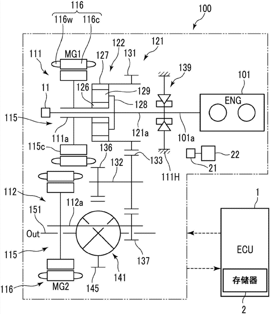
[0026] Such as figure 1 As shown, the vehicle 100 is a so-called hybrid vehicle in which an internal combustion engine 101 and rotating electric machines 111, 112 are mounted as power sources. Each of the rotary electric machines 111, 112 functions as a motor generator (MG). That is, the vehicle 100 includes the rotating electric machine system according to the present embodiment. The vehicle 100 is constructed such that the entire vehicle is controlled by an electronic control unit (ECU) 1 and, for example, these engine 101 and rotary electric machines 111, 112 are efficiently driven. The power of these engine 101 and rotary electric machines 111 and 112 is transmitted to drive shaft 151 via power transmission mechanism 121 and the like. The power transmission mechanism 121 functions as a differential device. Thus, wheels (not shown) rotate, and the vehicle 100 travels.
[0027] The engine 101 converts combustion energy of fuel into rotational driving force, and outputs t...
no. 2 example
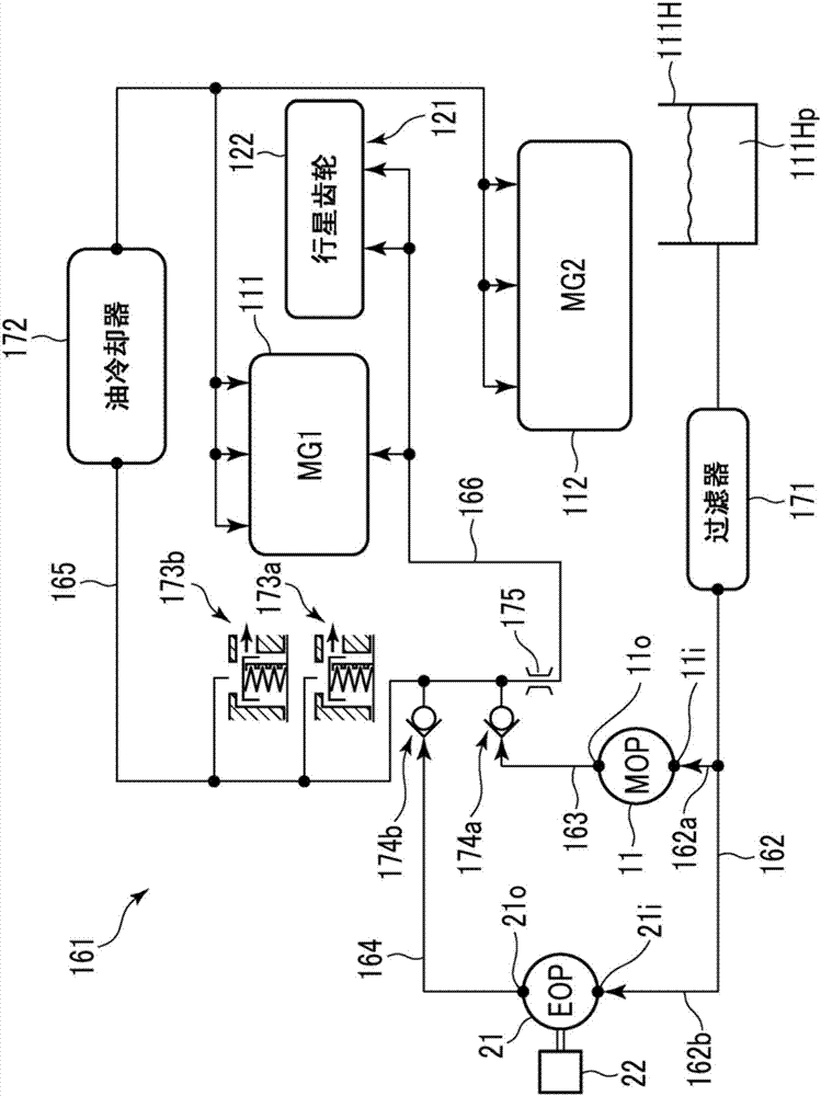
[0092] Such as Figure 7A to Figure 7B As shown, the pressure regulating valve 41 is installed on the discharge side of the MOP 11 in the first distribution oil passage 163 of the hydraulic circuit 161, the MOP 11 and the EOP 21 are incorporated in the hydraulic circuit 161, and the pressure regulating valve 42 is installed in the hydraulic circuit 161 The discharge side of the EOP 21 in the second distribution oil passage 164 . The pressure regulating valve 41 is set to reduce the hydraulic pressure of the lubricating oil discharged to the first distribution oil passage 163 to a certain pressure so as not to be affected by pressure fluctuations discharged from the MOP 11 . The pressure regulating valve 42 is set to reduce the hydraulic pressure of the lubricating oil discharged to the second distribution oil passage 164 to a certain pressure so as not to be affected by pressure fluctuations discharged from the EOP 21 . That is, the pressure regulating valves 41, 42 constitut...
no. 3 example
[0102] Next, Figure 9 is a flowchart showing a rotating electric machine system according to a third embodiment of the present invention. As an example, a case will be described where the configuration of the present embodiment is basically the same as that of the first embodiment described above, however, the configuration of the present embodiment is not limited to this configuration. Of course, the configuration of the present embodiment can be applied to the second embodiment. Such as Figure 9 As shown, the ECU 1 executes processing similar to steps S11 to S13 in parallel with step S18 according to the first embodiment described above, in which the ECU 1 repeatedly determines whether the elapsed time measured by the timer from when the supply of lubricating oil is increased The set elapsed time threshold is exceeded. When the ECU 1 determines that there is no possibility of occurrence of electrolytic corrosion, the ECU 1 interrupts the process of increasing the supply...
PUM
 Abstract
Description
Claims
Application Information
 - R&D
- Intellectual Property
- Life Sciences
- Materials
- Tech Scout
- Unparalleled Data Quality
- Higher Quality Content
- 60% Fewer Hallucinations
Browse by: Latest US Patents, China's latest patents, Technical Efficacy Thesaurus, Application Domain, Technology Topic, Popular Technical Reports.
© 2025 PatSnap. All rights reserved.Legal|Privacy policy|Modern Slavery Act Transparency Statement|Sitemap|About US| Contact US: help@patsnap.com


