
System and method for photon sampling based on OEO

A sampling system and photon technology, applied in lasers, phonon exciters, laser parts, etc., can solve the problems of difficult to achieve large serial-to-parallel conversion ratio, high average power of sampling pulses, limited number of wavelengths, etc. Realize high-speed real-time sampling, simple and easy operation, and save system cost

Inactive Publication Date: 2018-04-06
TIANJIN UNIV
View PDF7 Cites 7 Cited by
  • Summary
  • Abstract
  • Description
  • Claims
  • Application Information

AI Technical Summary

Problems solved by technology

However, there are technical difficulties in directly adopting the wave-time division optical pulse scheme under high-speed sampling conditions
First of all, in order to achieve high time resolution, each optical pulse needs to be a narrow pulse, and the spectral width of each wavelength pulse is quite wide. The number of wavelengths of the entire wave time division source is limited, and it is difficult to achieve large serial-to-parallel conversion. Compare
Secondly, the large peak-to-average ratio of the narrow pulse source determines that the average power of the sampling pulse entering the photodetector cannot be too high, so the noise of the photoelectric conversion will directly limit the accuracy of the system

Method used


Image

  • System and method for photon sampling based on OEO
  • System and method for photon sampling based on OEO
  • System and method for photon sampling based on OEO

Examples


Embodiment Construction

[0017] The technical solution of the present invention will be further described in detail below in conjunction with the accompanying drawings and specific embodiments, and the described specific embodiments are only for explaining the present invention, and are not intended to limit the present invention.

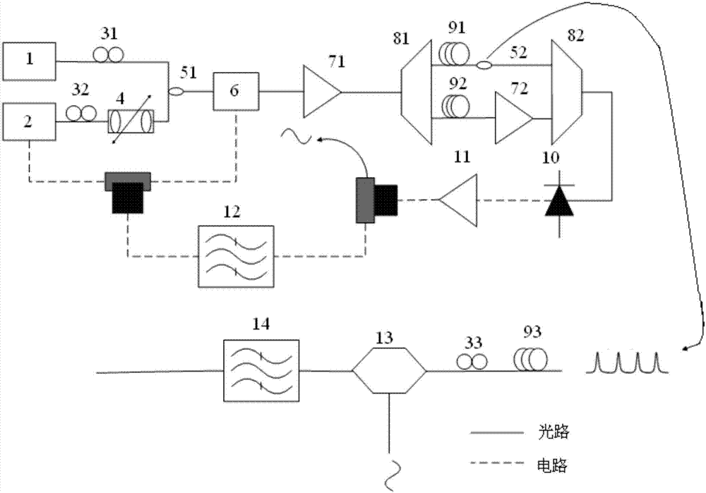
[0018] Such as figure 1 As shown, an OEO-based photon sampling system proposed in the present invention includes an OEO-based optical narrow pulse source and a time-domain Fourier transform system.

[0019] The OEO-based optical narrow pulse source is generated by a wavelength double-ring OEO structure, and the wavelength double-ring OEO structure includes a directly modulated laser 2, an adjustable laser 1, a variable optical delay line 4, a first polarization controller 31, a second Polarization controller 32, first optical coupler 51, second optical coupler 52, phase modulator 6, first erbium-doped fiber amplifier 71, second erbium-doped fiber amplifier 72, first wavele...


PUM

PropertyMeasurementUnit
Center frequencyaaaaaaaaaa

Abstract

The present invention discloses a system for photon sampling based on an OEO. The system for photon sampling based on the OEO comprises an optical narrow pulse source based on the OEO and a time domain Fourier transform system. The optical narrow pulse source based on the OEO is generated by a wavelength double-ring OEO structure, a directly modulated laser and a phase modulator are integrated into the wavelength double-ring OEO structure, microwave signals are generated by the OEO structure, the directly modulated laser is modulated to generate optical narrow pulses, the phase modulator is employed to broaden the pulse width to obtain wide-spectrum narrow pulses, and a long fiber dispersive medium is employed to perform dispersion walk-off of the narrow pulses to form constant-amplitude chirped narrow pulses and perform signal sampling. The system and the method employ a characteristic that the OEO structure directly generates signals with high repetition frequency and low phase noise, and combine the time domain Fourier transform system to simplify a production process and an optical serial-parallel converting process of the pulse source with a high repeat rate in photon samplingand have a characteristic of ultralow jittering. The system and the method for photon sampling based on the OEO can be widely applied to the fields of optical communication, optical analog-digital conversion, laser radar, microwave photonics, etc.

Description

technical field [0001] The invention relates to a photon sampling system based on OEO (optical oscillator), in particular to an optical narrow pulse source and time-domain Fourier transform sampling system based on OEO. Background technique [0002] Digital signal processing technology with high flexibility and high reliability has brought revolutionary development to all aspects of human society. To realize the conversion from analog signal to digital signal, analog to digital conversion (Analog to Digital Converter, referred to as ADC) is its key technology. With the continuous improvement of people's requirements for the rate and accuracy of information cognition, acquisition, and transmission, people's demand for ADC technology with high bandwidth, high sampling rate, and high quantization accuracy is also increasingly urgent. However, the traditional electrical ADC technology is limited by the electronic aperture jitter and electronic transit time uncertainty, and its ...

Claims


Application Information

Patent Timeline
IPC IPC(8): H01S3/067H01S3/11
CPCH01S3/067H01S3/06712H01S3/06716H01S3/11
Inventor 于晋龙包文强王菊
Owner TIANJIN UNIV
Learn More