Successive Approximation Analog-to-Digital Converter Based on Asymmetric Differential Capacitor Array
A successive approximation, analog-to-digital converter technology, applied in the direction of analog/digital conversion, code conversion, instruments, etc., can solve the problems of increased power consumption and low precision, so as to save capacitance and area, and reduce capacitance area , The effect of reducing power consumption
- Summary
- Abstract
- Description
- Claims
- Application Information
AI Technical Summary
Problems solved by technology
Method used
Image
Examples
Embodiment 1
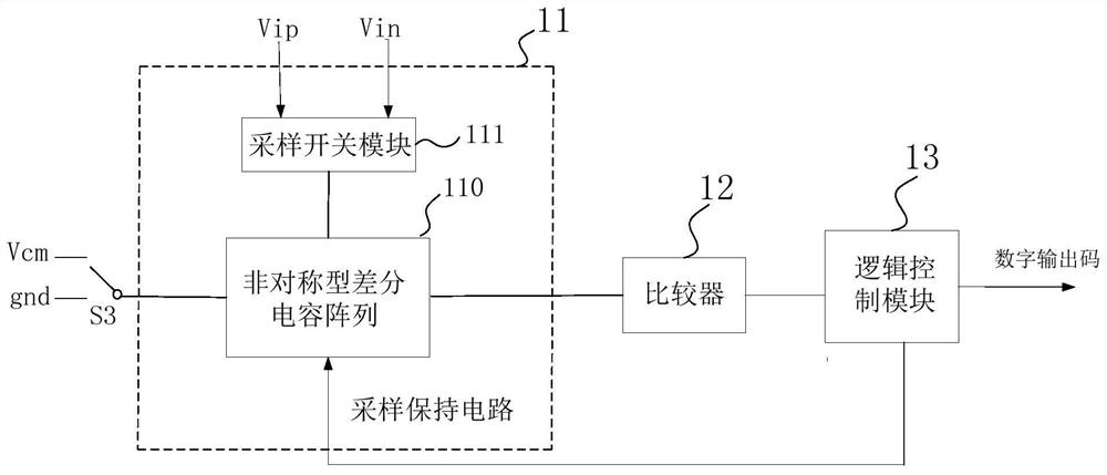
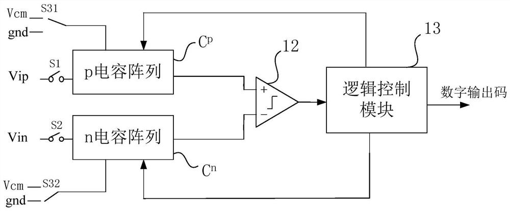
[0037] See figure 1 , figure 1It is a logical schematic diagram of a successive approximation analog-to-digital converter based on an asymmetrical differential capacitor array provided by an embodiment of the present invention. The successive approximation analog-to-digital converter based on the asymmetric differential capacitor array of this embodiment includes a sample-and-hold circuit 11 , a comparator 12 and a logic control module 13 . The sample-and-hold circuit 11 includes an asymmetric differential capacitor array 110 and a sampling switch module 111, wherein the first input terminal of the asymmetric differential capacitor array 110 is selectively electrically connected to the common-mode voltage terminal Vcm and the ground terminal through the single-pole double-set switch S3 gnd, the second input terminal of the asymmetric differential capacitor array 110 is electrically connected to the output terminal of the sampling switch module 111, the third input terminal of...
Embodiment 2
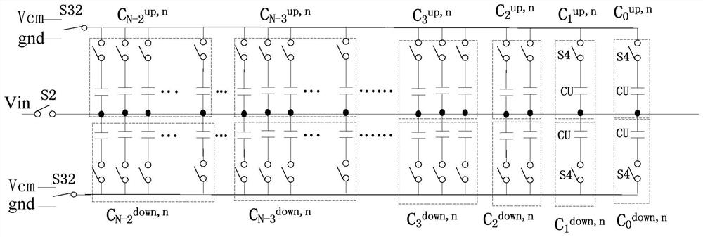
[0043] See image 3 , image 3 It is a schematic structural diagram of an n-capacitor array provided by an embodiment of the present invention.
[0044] Such as image 3 shown, the n-capacitor array C n Including an N-1-bit upper capacitor group C connected in parallel between the sampling switch S2 and the second single-pole double-setting switch S32 0 up,n to C N-2 up,n and N-1 lower capacitor bank C 0 down,n to C N-2 down,n , where, N-1 upper capacitor group C 0 up ,n to C N-2 up,n Capacitor bank C on bit 0 0 up,n and the 1st upper capacitor bank C 1 up,n Both include a capacitor unit, the capacitance values are C and 2C respectively; the capacitor group C on the N-2 position N-2 up,n It is a binary capacitor group, including N-2 capacitor units, and the capacitance value of the N-2 capacitor units is 2 N-3 C....4C, 2C, 2C, where N≧4. It is worth noting that the 2nd upper capacitor bank C 2 up,n To the N-2th upper capacitor group C N-2 up,n The c...
Embodiment 3
[0056] Please also see Figure 5 to Figure 8 , Figure 5 to Figure 8 It is a working principle diagram of an asymmetric differential capacitor array applied to a 4-bit successive approximation analog-to-digital converter provided by an embodiment of the present invention. This embodiment takes a 4-bit successive approximation analog-to-digital converter as an example to specifically illustrate the working principle of the successive approximation analog-to-digital converter based on the asymmetric differential capacitor array of the present invention.
[0057] (1) The analog input signals SVip and SVin are held by the sample-and-hold circuit 11, and the p-capacitor array C p The connection mode of the upper capacitor is (gnd, gnd), and the connection mode of the lower capacitor is (Vcm, Vcm); the n capacitor array C n The connection mode of the upper capacitor is (gnd, gnd, gnd, gnd), and the connection mode of the lower capacitor is (Vcm, Vcm, Vcm, Vcm). After sampling, th...
PUM
 Abstract
Description
Claims
Application Information
 - R&D
- Intellectual Property
- Life Sciences
- Materials
- Tech Scout
- Unparalleled Data Quality
- Higher Quality Content
- 60% Fewer Hallucinations
Browse by: Latest US Patents, China's latest patents, Technical Efficacy Thesaurus, Application Domain, Technology Topic, Popular Technical Reports.
© 2025 PatSnap. All rights reserved.Legal|Privacy policy|Modern Slavery Act Transparency Statement|Sitemap|About US| Contact US: help@patsnap.com


