Electron device flash spray circulation cooling system with self-optimizing characteristic

A circulating cooling system and electronic device technology, which is applied in the direction of fluid circulation arrangements, machines using refrigerant evaporation, superheaters, etc., can solve the problems of significant cooling effect, environmental pollution, refrigerant waste, etc., and achieve omission of heating devices, The effect of expanding the scope of use and improving heat exchange efficiency

Active Publication Date: 2018-04-10
XI AN JIAOTONG UNIV
View PDF9 Cites 4 Cited by
  • Summary
  • Abstract
  • Description
  • Claims
  • Application Information

AI Technical Summary

Problems solved by technology

[0005] However, most of the current flash spray cooling devices are open design, resulting in the waste of refrigerant and pollution to the environment; the rare closed circulation system does not effectively solve the problem of system operation stability, limited heat dissipation capacity, and compressor Mismatch with the nozzle flow rate, spray distance and spray chamber inclination angle have a significant impact on the cooling effect

Method used


Image

  • Electron device flash spray circulation cooling system with self-optimizing characteristic
  • Electron device flash spray circulation cooling system with self-optimizing characteristic
  • Electron device flash spray circulation cooling system with self-optimizing characteristic

Examples


Embodiment Construction

[0031] In conjunction with the following drawings, the present invention is further described by examples.

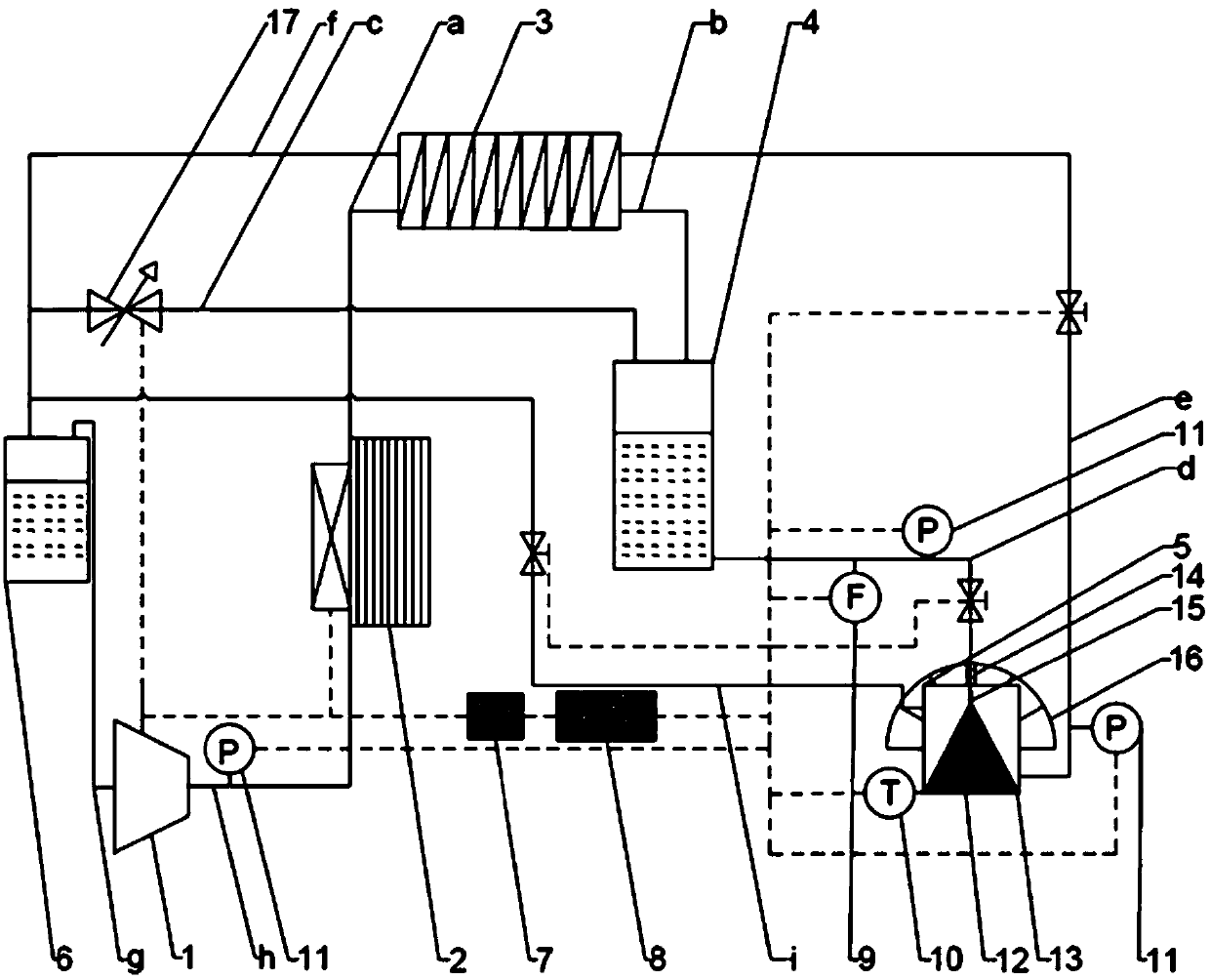
[0032] see figure 1 As shown, the present invention has a self-optimizing feature of the flash spray circulation cooling system for electronic devices, including a compressor 1, a forced air-cooled condenser 2, a regenerator 3, a liquid storage tank 4, a spray chamber 5, and a gas-liquid separator 6. Flow regulation bypass c and control system.

[0033]Compressor 1 is a variable frequency rotor compressor; the outlet of compressor 1 is connected to the inlet of condenser 2 through pipe h, the outlet of condenser 2 is connected to the inlet of the first channel of regenerator 3 through pipe a, and the first channel of regenerator 3 The outlet of a channel is connected to the inlet of the liquid storage tank 4 through the pipeline b, the lower outlet of the liquid storage tank 4 is connected to the inlet of the spray chamber 5 through the pipeline d, and the lower liquid...


PUM


Abstract

The invention discloses an electron device flash spray circulation cooling system with a self-optimizing characteristic. The electron device flash spray circulation cooling system with the self-optimizing characteristic comprises a compressor, a condenser, a heat regenerator, a liquid storage tank, a mist spraying cavity and an air-liquid separator, wherein an outlet of the compressor is connectedwith an inlet of the condenser through a pipeline; the condenser is connected with an inlet of a first passage of the heat regenerator through a pipeline; an outlet of the first passage of the heat regenerator is connected with an inlet of the liquid storage tank through a pipeline; a lower outlet of the liquid storage tank is connected with an inlet of the mist spraying cavity through a pipeline; a lower liquid outlet of the mist spraying cavity is connected with an inlet of a second passage of the heat regenerator through a pipeline; an upper air outlet of the mist spraying cavity is connected with an inlet of the air-liquid separator through a pipeline; an outlet of the second passage of the heat regenerator is connected with the inlet of the air-liquid separator through a pipeline; and the air-liquid separator is connected with an inlet of the compressor through a pipeline. The system realizes optimal control over heat exchange intensity by regulating the parameters such as the opening degree of a bypass valve, the frequency of the compressor and the height and dip angle of mist spraying, and rapidness and stability of the system are guaranteed.

Description

technical field [0001] The invention belongs to the technical field of refrigeration, and in particular relates to an electronic device / chip flash spray circulation cooling system. Background technique [0002] Chip technologies such as CPU chips, laser semiconductor chips, LED chips, and electronic devices such as laser weapons and active phased array radars have developed towards high integration and high power in recent years. Take the LED chip as an example, only 20%-30% of the electric energy is converted into light energy when it is working, and the remaining 70%-80% of the electric energy is converted into heat energy. Poor heat dissipation will cause the junction temperature of the chip to rise, resulting in spectral Offset, life reduction and other issues. Similarly, for the CPU chip, if it exceeds 60°C, the possibility of chip burnout increases greatly. According to investigations, 60%-70% of CPU chip damage is related to excessive temperature. For high-power chi...

Claims


Application Information

Patent Timeline
Patent Type & Authority Applications(China)
IPC IPC(8): F25B19/04F25B40/06F25B43/00F25B41/00F25B41/40
CPCF25B19/04F25B40/06F25B41/00F25B43/006
Inventor 周致富林彦可陈斌方宇唐鸿林
Owner XI AN JIAOTONG UNIV
Why Eureka
Try Eureka