Float glass defoaming process
A float glass and defoaming technology, which is applied in glass furnace equipment, glass manufacturing equipment, manufacturing tools, etc., can solve the problems of large pollution emissions and high energy consumption, and achieve the effects of environmental protection, good purification effect, and reduced SO2 content
- Summary
- Abstract
- Description
- Claims
- Application Information
AI Technical Summary
Problems solved by technology
Method used
Image

Examples
Embodiment 1
[0026] Degassing of float glass
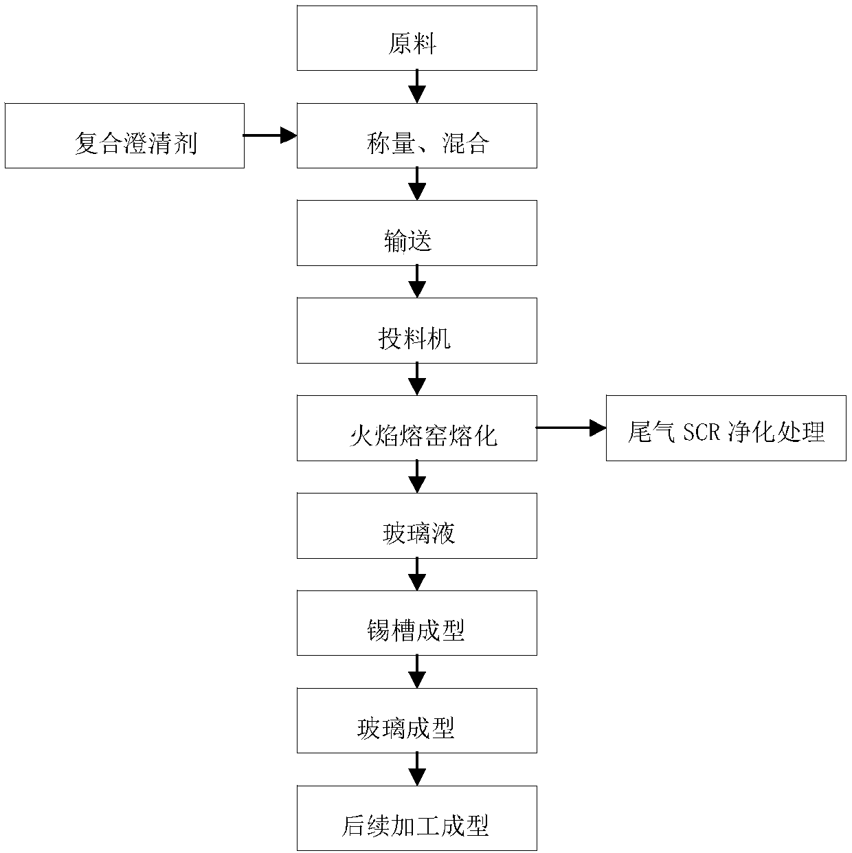
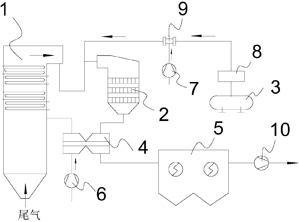
[0027] Such as figure 1 In the float glass preparation process shown in the figure, 1000kg of material is weighed according to the proportion of raw materials for float glass production, and 7kg of compound clarifying agent is added. Among them, Glauber's salt 5kg and sodium nitrate 2kg. Feed the prepared float glass raw material into the kiln, gradually heat up to 1450°C, and melt it into molten glass. After the molten glass is melted and clarified, the original pieces of float glass of various specifications are manufactured according to the conventional process. For the exhaust gas produced in the process of preparing float glass, the exhaust gas is sent to the SCR denitrification system to increase NH 3 Injecting 1 cubic meter per hour, reducing NOx to harmless N 2 and H 2 O. Sampling, monitoring and analysis of the tail gas discharged from the kiln showed that the SO in the flue gas 2 The content is 210-240ppm, and the nitrogen ox...
Embodiment 2
[0030] Degassing of float glass
[0031] Weigh 1000kg of material according to the mixing ratio of raw materials for float glass production, and add 7kg of composite clarifying agent. Among them, Glauber's salt 2kg and sodium nitrate 5kg. Feed the prepared float glass raw material into the kiln, gradually heat up to 1450°C, and melt it into molten glass. After the molten glass is melted and clarified, the original pieces of float glass of various specifications are manufactured according to the conventional process. For the tail gas produced in the process of preparing float glass, the tail gas is transported to the SCR denitrification system, the SCR denitrification system is the same as in Example 1, and the NH 3 The injection volume is 2.5 cubic meters per hour, reducing NOx to harmless N 2 and H 2O. Sampling, monitoring and analysis of the tail gas discharged from the kiln showed that the SO in the flue gas 2 Content of 90-130ppm, nitrogen oxide content of 320-400 p...
Embodiment 3
[0036] Degassing of float glass
[0037] Weigh 1000kg of material according to the mixing ratio of raw materials for float glass production, and add 7kg of composite clarifying agent. Among them, Glauber's salt 3.5kg and sodium nitrate 3.5kg. Feed the prepared float glass raw material into the kiln, gradually heat up to 1450°C, and melt it into molten glass. After the molten glass is melted and clarified, the original pieces of float glass of various specifications are manufactured according to the conventional process. For the tail gas produced in the process of preparing float glass, the tail gas is transported to the SCR denitrification system, the SCR denitrification system is the same as in Example 1, and the NH 3 The injection volume is 1.5 cubic meters per hour, reducing NOx to harmless N 2 and H 2 O. Sampling, monitoring and analysis of the tail gas discharged from the kiln showed that the SO in the flue gas 2 Content of 170~210ppm, nitrogen oxide content of 320...
PUM
 Abstract
Description
Claims
Application Information
 - R&D Engineer
- R&D Manager
- IP Professional
- Industry Leading Data Capabilities
- Powerful AI technology
- Patent DNA Extraction
Browse by: Latest US Patents, China's latest patents, Technical Efficacy Thesaurus, Application Domain, Technology Topic.
© 2024 PatSnap. All rights reserved.Legal|Privacy policy|Modern Slavery Act Transparency Statement|Sitemap